Tiltmeters are designed to monitor the inclination and vertical rotation of structures. If you are to ask what a tiltmeter measures, the answer is simple; it measures tilt. Tilt in any structure can be caused by various construction activities like excavation, tunneling, or de-watering that may negatively affect the ground that supports the structure.
Continue reading to know the operating principle of a tiltmeter, how is it installed, and how are the readings taken.
How Does a Tiltmeter Work?
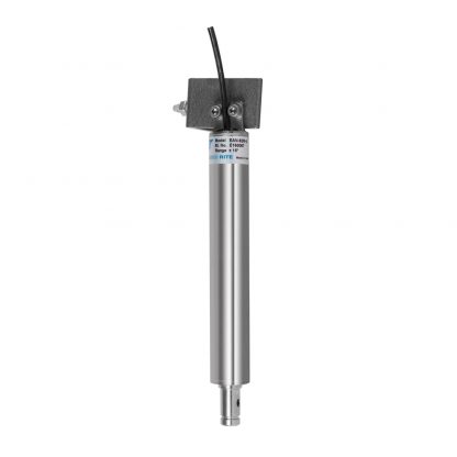
It is a very common query – How does a tiltmeter work? Let’s take a look at Encardio Rite’s Tiltmeter to understand its working. Encardio Rite Model-90M Tiltmeter is built around a precision accelerometer and suitable signal conditioning circuit mounted inside stainless steel housing.
The accelerometer senses force of acceleration due to gravity which is maximum when the accelerometer is rotated to a full 90-degree tilt position. The same force of acceleration due to gravity is zero (minimum) when the tilt angle of the accelerometer is zero.
For in-between tilts, the force experienced by the accelerometer is equal to the product of the sine of tilt angle and acceleration due to gravity. The tilt sensor thus provides a bipolar DC voltage output proportional to the sine of the tilt angle measured by the tiltmeter. The output is zero volts for a truly vertical position. This is how a tiltmeter measures the tilt.
The sensor provides a relatively low-cost tilt measurement solution but still offers excellent resolution, long-term stability, and low thermal sensitivity. The tiltmeter can be fixed to any vertical surface, horizontal floor, or ceiling using suitable mounting accessories consisting of brackets and anchors.
The EAN-90M tiltmeter is not designed for absolute determination of tilt in structures. It measures the change in the tilt of a structure to which the sensor is attached. The initial tilt reading for each tilt sensor is recorded after it has been mounted on the structure to be monitored. Subtracting the initial tilt reading from the consequent tilt reading gives a change in the tilt of the structure over some time. In this manner, tiltmeter monitoring is carried out.
Now that we are aware of what a tiltmeter is used for and its works, let’s take a look at its installation procedure.
Read More: What are Tiltmeters & Where are They Used?
Tools & Accessories Required for Tiltmeter Installation
The following tools and accessories are required for the proper installation of the tilt meters.
- Power drill
- Concrete / Masonry drill bit 8 mm
- Spanner 8/9, 12/13 mm
- Allen key 5 mm
- Cloth for cleaning
How is a Tiltmeter Installed?
The Model EAN-90M tiltmeter sensor installation can take place by fixing it to a vertical surface, suspending it from the ceiling, or mounting it on the floor with the help of a suitable mounting arrangement/bracket available from Encardio Rite as optional accessories.
Tiltmeter Installation on Vertical Surface
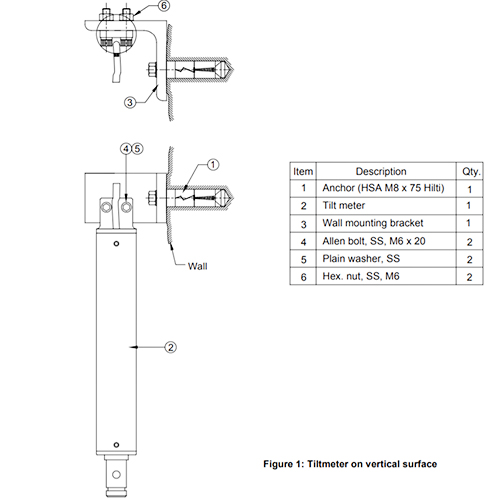
- Drill an 8 mm Φ x 50 mm deep hole for Hilti anchor HSA M8 x 75 or equivalent on the wall of which change in tilt has to be measured.
- Insert anchor in the drilled hole.
- Mount the tiltmeter bracket on the anchor and tighten it slightly.
- Fix the tiltmeter on the mounting bracket with two M6 x 20 mm Allen bolts.
- Connect the tiltmeter with the read-out unit.
- Tighten the anchor and Allen bolts/nuts so that the tiltmeter reads almost vertically on the read-out unit.
Tiltmeter Installation on Horizontal Surface
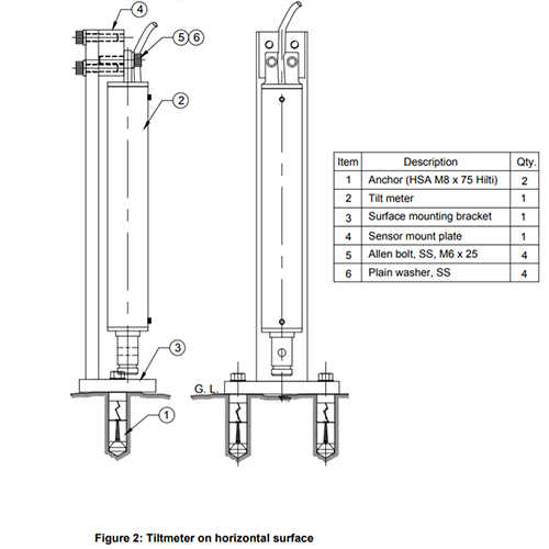
- Using the mounting bracket as a template, mark the position of two mounting holes.
- Visually ensure that the two-hole positions are almost aligned along the axis at which tilt has to be measured.
- Drill two 8 mm Φ x 50 mm deep holes for Hilti anchor HAS M8 x 75 or equivalent.
- Insert anchors in drilled holes.
- Mount the tiltmeter bracket on the anchors and tighten slightly.
- Fix the tiltmeter on the mounting bracket with two M6 x 20 mm Allen bolts. Connect the tiltmeter with the read-out unit.
- Tighten anchors and Allen bolts/nuts so that the tiltmeter reads almost vertically on the read-out unit.
Tiltmeter Installation on Roof
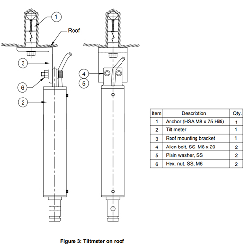
- Drill an 8 mm Φ x 50 mm deep hole for Hilti anchor HSA M8 x 75 or equivalent on the roof at which change in tilt has to be measured. Insert anchor in the drilled hole.
- Mount the tiltmeter bracket on the anchor and tighten it slightly.
- Fix the tiltmeter on the mounting bracket with two M6 x 20 mm Allen bolts.
- Connect tiltmeter with read-out unit.
- Tighten the anchor and Allen bolts/nuts so that the tiltmeter reads almost vertically on the read-out unit.
How to Read Tiltmeter?
Tiltmeter reading in a simple process. The output of the tiltmeter can be read by the Encardio Rite model EDI-53UTM portable digital read-out unit/data logger. The EAN-90M can also be read or logged from a remote location by an automatic data acquisition system like the Encardio Rite model EDAS-10.
The tilt meter is supplied with a 2 m built-in six-core cable. The cable can be terminated or extended to the nearest measurement station through a suitable junction box.
Read more: MEMS Tiltmeter- Installation Procedure & How does it work?
Connecting Tiltmeter to Digital Readout Unit
The tiltmeter can be connected to the Encardio Rite Model EDI-53UTM portable digital readout unit/data logger through a break-out box. Break-out box provides the mating circular connector to the read-out unit. The cable can also be extended through the break-out box. It is also equipped with a lightning arrestor.
Encardio Rite model EDI-53UTM portable digital readout unit/data logger reads sine of tilt angle when a parameter of a typical tiltmeter is fed. To read the sine of tilt angle, set up the EDI-53UTM channel as follows:
- Unit [UNITS] – No units (key 9)
- Initial reading [IR] – Set to zero
- Gauge factor [GF] – 2/tilt meter gage factor in volts/sin 90°
- Coeff of X² – Set to zero
- Decimal point [DP] – As required (recommended value is 4)
The tilt angle can be calculated by sin-1(observed value). For the bi-axial tilt meter, set up two channels (one for the A-axis and one for the B-axis) in a similar manner.