The portable tiltmeter is a high-resolution uniaxial tilt sensor that is designed to monitor inclination and vertical rotation in structures.
It is ruggedly built and has superior temperature stability. The tilt variations in a structure can be caused by construction activities such as excavation, tunneling, or dewatering that may affect the ground supporting the structure.
The changes in tilt can also occur from the loading of a structure, such as a dam during impoundment, a diaphragm wall during excavation, or a bridge deck due to wind and traffic.
The EAN-70M tilt measurement system consists of two components – a portable tiltmeter and several Aluminium tilt plates. Individual tilt plates are usually anchored to the structure, but may also be bonded to a smooth clean surface i.e. granite, stone, or tiles.
The user places the portable tiltmeter on the mounted tilt plate to get the tilt reading at that location. The portable tiltmeter has to be carried from one tilt plate to another to get readings at different locations. Although it is a uniaxial tiltmeter, it can also be used to take biaxial measurements at any particular location by rotating the tiltmeter by 90° on the tilt plate and taking a second reading.
Here is everything about a portable tiltmeter – its installation procedure and how to take readings from it.
What is a Portable Tiltmeter?
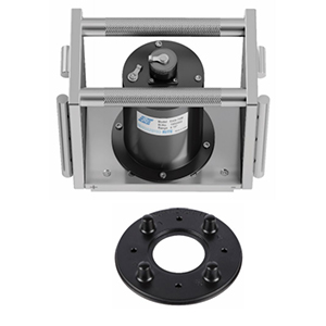
Encardio Rite deals with Model EAN-70M which is a portable tiltmeter, built around a precision accelerometer and suitable signal conditioning circuit mounted inside anodized aluminum housing.
The accelerometer senses the force of acceleration due to gravity which is maximum when the accelerometer is rotated to a full 90° tilt position and is zero (minimum) when the tilt angle of the accelerometer is 0°. For in-between angles, the force experienced by the accelerometer is equal to the product of the sine of tilt angle and acceleration due to gravity. The tilt sensor provides a bipolar DC voltage output which is proportional to the sine of tilt angle measured by the tiltmeter. The output is zero volts for a truly vertical sensor. The portable tiltmeter provides a comparatively low-cost tilt measurement solution with excellent resolution, long-term stability, and low thermal sensitivity.
The tiltmeter can be used to measure the change in the tilt of any vertical surface or horizontal floor by placing it on a suitable reference tilt plate, available separately. The EAN-70M is not intended for the absolute determination of the tilt of structures. It measures the change in the tilt of structures to which the reference tilt plate is attached. The initial tilt reading for each tilt plate is recorded after it is mounted on the structure to be monitored. Change in the tilt of structure over some time can be measured by subtracting the initial tilt reading from subsequent tilt readings.
What is a Tilt Plate?
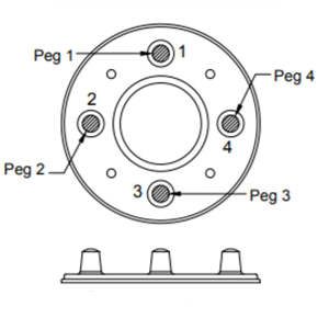 Figure 1: Tilt Plate
A tilt plate is an aluminum disc about 142 mm in diameter. It is fixed to the structure with four Hilti anchors HPS 1-6/15×40 # 260350 or equivalent. In case the structure has a smooth surface like marble or granite, the tilt plate may be bonded to it by epoxy.
The four pegs on the tilt plate are used to orient the tiltmeter. The horizontally mounted tilt plate allows tilt readings in two planes that are at 90° to each other. Whereas, the vertically mounted tilt plate allows tilt readings along one vertical plane only.
| Read More: What Are Tiltmeters And Where Are They Used? |
How is a Portable Tiltmeter Installed?
The tilt plates are fixed on structural members that are representative of a large structure. When a single location does not represent the structure, additional tilt plates are placed at other locations. The number of tilt plates needed is determined by the stiffness of the structure and the accuracy desired.
Stiffer structures require fewer plates. To achieve large accuracy, more plates are required. Tilt plates are generally placed with one set of pegs oriented to the expected direction of rotation. The location of the tilt plate shall be chosen such that they are easily accessible.
Orientation of horizontal tilt plates

Figure 2: Tilt mounting on the horizontal surface
Horizontal plates provide two planes of measurement. Plane A is defined by pegs 1 & 3. Peg 1 is usually oriented towards the direction of tilt. Plane B is defined by pegs 2 & 4. Peg 4 is usually oriented toward the direction of tilt.
Orientation of vertical tilt plates
Vertical tilt plates should be aligned so that a vertical line can be drawn through pegs 1 and 3.
Mounting procedure of tilt plates
Tilt plates can be fixed to the structure with anchors and screws or with grout. When a tilt plate experiences temperature changes or weather, a combination of both anchors and grout works best.
Anchors and screws
- Prepare a clean flat surface.
- Place the tilt plate on the structure in its intended orientation.
- Mark the location of anchors.
- Drill holes large enough and deep enough to accommodate anchors. Screw the tilt plate to the anchors.
- Check and ensure the correctness of the horizontal and vertical position of the tilt plate by using a spirit level.
Tools & accessories required for installation
- Hilti Impact fastener polyamide no. HPS 1-6/15X40 or equivalent
- Star head screwdriver
- Sprit level 150mm Drill bit 6mm
- Power drill machine
- Ballpoint hammer, 250 gm
How to Read Portable Tiltmeter?
Allow time for the tiltmeter to adjust to ambient temperature. If possible, store the tiltmeter at the same temperature as at the time of taking readings. Connect the tiltmeter to readout and power up. Take readings as follows:
Reading horizontal tilt plates
- Take reading in the plane “A” first. In the figure below, pegs 1 and 3 define the direction of plane “A”.
- Place “+” end of tiltmeter on peg 1, wait for reading to stabilize and record it. Rotate the tiltmeter 180° and place the “-“ end of the tiltmeter on peg 1, wait for the reading to stabilize, and record it.
- Repeat steps 2-3 times to ensure that the readings are repeatable. In theory, A+ and A – readings should be identical except for different signs (+/-).
- In practice, there is a difference up to 0.003 on Encardio Rite readout unit EDI-53UTM between two readings due to bias of the sensor and small irregularities in the tilt plate.
Figure 3 below shows the positioning of the portable tiltmeter on the tilt plate for taking readings in plane A
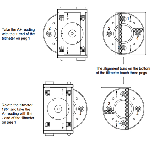 Figure 3: Taking readings in Plane A
Take readings in plane B next. Plane B is defined by the direction of pegs 2 and 4. Place the “+” end of the tiltmeter on peg 4, wait for the reading to stabilize, and record it.
Rotate the tiltmeter 180° and place the “-“ end of the tiltmeter on peg 4, wait for the reading to stabilize, and record it. Figures 1 & 2 explain the positioning of the portable tiltmeter on the tilt plate to take readings in planes A and B respectively.
Repeat steps 2-3 times to ensure readings are repeatable. In theory, B+ and B – readings should be identical except for different signs (+/-). In practice, there is a difference up to 0.003 on Encardio Rite readout unit EDI-53UTM between the two readings due to the bias of the sensor and small irregularities in the tilt plate.
Figure 4 below shows the positioning of the portable tilt meter on the tilt plate for taking readings in plane B.
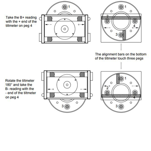 Figure 4: Taking readings in Plane B
Reading vertical tilt plates
Vertical tilt plate allows reading in tilt plane A defined by the direction of pegs 1 and 3. The tiltmeter is aligned using alignment bars at the ends of the tiltmeter.
Place the “+” end of the tiltmeter against peg 1, wait for the reading to stabilize, and record it. Refer to figure 6.
Place “-” end tilt meter against peg 1, wait for readings to stabilize, and record it.
Repeat these steps three times to ensure that you have good repeatable readings.
Repeat steps two to three times to ensure readings are repeatable. In theory, readings should be identical except for different signs (+/-).
In practice, there is a difference up to 0.003 on Encardio Rite readout unit EDI-53UTM between two readings due to bias of the sensor and small irregularities in the tilt plate.
Figure 5 below shows the position of the portable tiltmeter on the tilt plate for taking readings in vertical plane B.
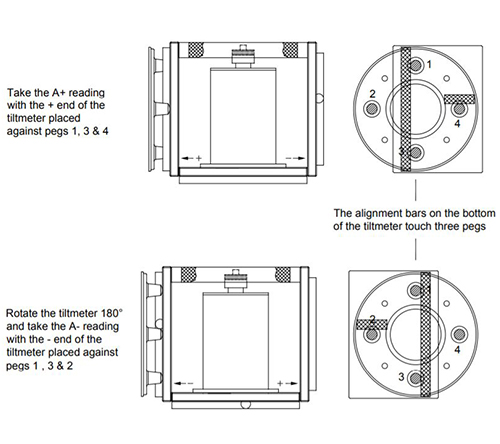 Figure 5: Taking tiltmeter readings in the vertical plane
Tiltmeter – How to take Readings
One is generally interested in finding changes in the tilt of a structure. To find a change in tilt, subtract the initial tilt from the current tilt and convert the result into degrees or displacement.
Displayed readings
Encardio Rite readout unit Model EDI-53UTM displays the readings in terms of sin (tilt angle).
Displayed readings = sin (A)
Where A = angle of tilt
Combining + and – readings
Obtain two readings for each tilt plane, a “+” reading and a “-“reading. In the data reduction process, add the two readings to eliminate sensor bias. Denote this value by “DIFF” (algebraic difference). A positive DIFF value indicates tilt toward the + end of the tilt meter.
DIFF = (+ reading) – (- reading)
Calculating tilt
To convert the DIFF value to tilt in degrees, divide it by 2 because the DIFF value comprises two readings.
Take the inverse sine of this value to get the angle of tilt in degrees.
Angle of tilt = sin-1 (DIFF/2)
To calculate the change in tilt use the following formula:
Change in tilt = sin-1 (DIFF2/2) – sin-1(DIFF1/2)
Where DIFF1 is the initial reading (tilt reading taken just after installation) and DIFF2 is the current tilt reading (reading taken on a subsequent date)
Angle of tilt = sin-1 (DIFF/2)
To calculate the change in tilt use the following formula:
Change in tilt = sin-1 (DIFF2/2) – sin-1(DIFF1/2)
Where DIFF1 is the initial reading (tilt reading taken just after installation) and DIFF2 is the current tilt reading (reading taken on a subsequent date).
That was all about portable tiltmeters – installation procedure, how to take readings, and reduce data from the captured readings.
If you have any questions, feel free to drop them in the comments section below.