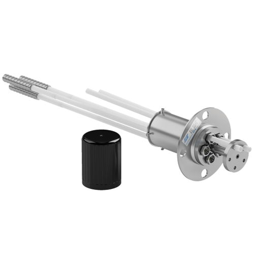
Encardio Rite Mechanical Borehole Extensometer Model EDS 63U/D is befitted for upward, downward, or inclined boreholes. It is specifically designed to assist civil engineers and geologists with the measurement of deformation of rock mass and adjacent or surrounding soul. It essentially consists of one or more anchors and a reference plate.
Let’s look at the Mechanical Borehole extensometer installation procedure.
Borehole extensometer installation procedure- Tools & accessories required
1. You will require the listed tools and accessories to successfully install a multi-position borehole extensometer:
- Loctite 290 and Loctite 415 or equivalent
- Acetone (commercial)
- Spanner size 22 Screwdriver
- Allen key
- Hacksaw with 150 mm blade
- Pliers 160 mm 150 mm flat file
- Tube cutter M6 threading tap with handle
- M6 threading die with handle
- Wire brush
- Cloth for cleaning (lintless)
- Insulation tape
- Micrometre depth gage 100 mm rang
Borehole Extensometer Installation Procedure with Fibreglass rod assembly
NOTE: Please keep in mind that the procedure described below is used to install an Encardio Rite borehole extensometer up to 6 points in a downward sloping hole with the help of groutable anchors. If you’re looking to install in an upward to horizontally-sloping borehole, using packer anchors, alter the procedure as required.
Site preparation before the borehole extensometer installation procedure:
2. Using the drilling machine, make a hole of 102mm diameter with a depth of 0.5 m – 1 m more than the length of the deepest anchor.
NOTE: In case you’re looking to mount the Mechanical borehole extensometer horizontally, it is advised to provide, if design allows, a downward slope of 5 degrees or more to the borehole. Doing so will promote the grouting of the anchor, allowing the grout to readily flow in.
- Where the hole commences, stretch the diameter of the hole to 125 mm up to a depth of 225 mm. This is done to make way for the wrapping outside of housing with rags or jute cloth strips covered in cement.
- Take the reference head assembly and insert it in the centre of the 125 mm borehole. Taking holes on the flange as a reference, drill four holes 18 mm diameter x 150 mm deep for fastening the flange to the borehole. Once done, remove the reference head assembly from the borehole.
3. Clean the hole up to the bottom by pumping in freshwater.
Borehole Extensometer Installation Procedure (Fibreglass rod assembly):
- In case the installation requires less than six points, use a standard rubber plug, steel washer, and hollow hex bolts to plug other points on the reference head assembly.
- Identify the machined portion of the groutable anchor and apply Loctite 415 or equivalent on it. Utilizing Loctite 290 as thread sealant, screw male end connector of longest fibreglass rod assembly to groutable anchor. Doing so will also allow the nylon tubing to strongly grip the groutable anchor.
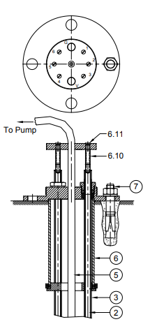
- Referring to the image above, separate the cover (6.13) from the flanged housing (6.1), and place the latter on the ground. Once done, loosen all hollow bolts (6.6) minutely.
4. Implant the groutable anchor in the borehole until the fibreglass rod can be seen 1 m – 1.5 m outside the borehole. To bare the female connector, trim the nylon sleeve by around 10 mm.
WARNING! Please be careful while handling fibreglass rods as they are supplied in coil form using cable ties. They are stiff in texture and nature and may snap while unwinding and lead to personal injury.
- The 5th step of the Mechanical borehole extensometer installation procedure is to navigate the end of the fibreglass rod into the corresponding hole in the guide plate (6.2), only to come out through the flanged housing top (6.1) marked “1”. You will need to bend the fibreglass to do this step. Find the setting spacer (6.10) which is located between the reference plate (6.9) and female connector end of fibreglass rod. Insert a screw through the reference plate hole and a screw through the setting spacer into the female connector end. When stretched, the reference button will be placed at a depth of 25 mm from top of the reference plate. To alter this distance, use a different length setting spacer (6.10).
5. If the hole in the reference plate is not in alignment with the hole marked “1” in flanged housing, all you have to do is loosen the Allen head bolt (6.8), align it, and tighten it afterwards.
NOTE: In case you’re planning an extension of the sidewall and roof, it is advised to use a 5- 10 mm setting spacer (6.10). Likewise, in a vertical down borehole, it is recommended to use a setting spacer of 40-45 mm.
6. Using a 22mm spanner, tighten the hollow bolt so that the nylon tube is sealed and secure. However, make sure you don’t squeeze too much as it may restrict the free movement of the female end connector inside the nylon tube.
NOTE: While handling the above method for horizontally sloping boreholes, you need to be extra cautious while tightening the hollow bolts as there is a possibility of the grout leaking through into the reference head assembly during the grouting process.
NOTE: To be absolutely sure with the identification of anchors at a later date, make sure to always assemble and mount the deepest anchor first. Holes on top of flanged housing are marked clockwise with identification numbers 1, 2, 3, V, 4, 5, 6, and G respectively.
Read more: Multipoint Borehole Extensometer- Introduction, Application, and System Requirements
7. The next step is to install all the fibreglass connection rods in descending order of their length
NOTE: Pay extra attention during the borehole extensometer installation procedure to ensure that the extensometer assembly does not drop into the borehole accidentally. For this, you need to secure it properly with the help of a safety rope attached to the anchor.
8. Install the grout tube during the borehole extensometer installation procedure. Usually, the lower end of the grout tube is kept at a level higher than the anchor closest to the borehole face. When the last anchor is inserted into the borehole, the lowest end of the grout tube is tied with a cable tie to fibreglass connecting rod. To determine the length of the grout tube ensure that around 1.5 m is outside the flanged housing (6.1) for ease in attaching it to the grout pump.
NOTE: When handling the upward to the horizontally sloping borehole, ensure that the grout tube is 1.5m longer than the depth of the deepest anchor and is taped about 300 mm below the far end of the anchor. Using an insulation tape, attach the grout tube at every 2m to the nylon tube to prevent it from swinging loose.
9. As described in the section below, install an air vent tube of 2mm long, ensuring that the grout should cover the anchor closest to the mouth or be around 1 m from the face of the borehole whichever distance is less. It is a rule that the lower end of the air vent tube is always at a higher level than the lower end of the grout tube.
NOTE: When dealing with the borehole extensometer installation procedure of the upward to horizontal sloping borehole, the air vent placement is a little bit different. It is placed at 0.5m longer than the depth of the deepest anchor and taped around 50 mm above the far end of the anchor. Making use of insulation tape, fix the air vent tube at every 2m interval to the nylon tube to avoid any loose ends. Make sure that the top end of the air vent tube is at a higher level than the deepest anchor.
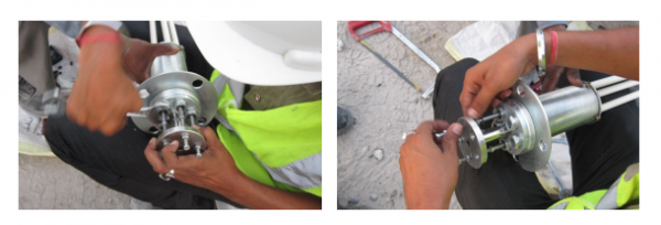
- Make use of rags or jute cloth, dip them in quick-setting cement water mix, and use them to wrap them to the flanged housing to create to 5mm thick layer. Once done, insert the housing in the borehole with the help of the to and fro screwing motion while ensuring that the annular space between the housing and borehole is sealed. Place the fasteners in the holes drilled specifically to grip the flanged housing. Once done, give enough time to let flanged housing set in the borehole.
10. The next step in the borehole extensometer installation procedure is to fill the cavity up to the tip of the air vent pipe with grout using a grouting machine. Let the grout set in for 8-12 hours.
NOTE: The composition of the grout is dependent on the site conditions. In the case of hard rock, 50 kg of cement with 30 kg of water has been successfully used at some project sites.
NOTE: Please ensure that the grout is covering the anchor closest to the mouth or is around 1m from the face of the borehole, whichever distance is less.
CAUTION: Take special care to ensure that there is no overflowing of grout into the flanged housing. Overflowing may allow it to enter the protective nylon tubing, leading to a jam in the setting rods.
11. Once the 8-12 hour period is over, pump grout into the system again to ensure that the anchors are completely grouted. The heavier grout likely settles down leaving water at the top, leading to the possibility that the anchors near the face of the borehole are not properly grouted. You can overcome this situation by filling the grout again and making sure that the water at the top is pumped out through the air vent tube.
Read more: Single Point Borehole Extensometer – Introduction & Operating Principle
CAUTION: To get correct displacement readings, ensure that all anchors are properly grouted. This problem may be particularly faced in the case of near anchors in downward boreholes and rear anchors in upward holes where the cement in grout settling down, there may only be water around the anchors.
- Unscrew the bolts and screws, and remove the setting spacers. Remove the grout and the vent tube from the roots by cutting the grout. Clean the reference head assembly properly.
- Fix reference buttons to the top of fibreglass rods.
12. Making use of the depth micrometer, record the initial reading along with the time, date, and temperature. Subsequent readings will determine the relative displacement between anchors.
Here we come to the end of the borehole extensometer installation procedure with Fibreglass rod assembly. If you have any doubts or questions, feel free to drop them in the comment section below.