In our last blog, we saw how a borehole extensometer is installed with the help of fiberglass connecting rods. Today, we look at the extensometer installation with stainless steel connecting rod assembly.
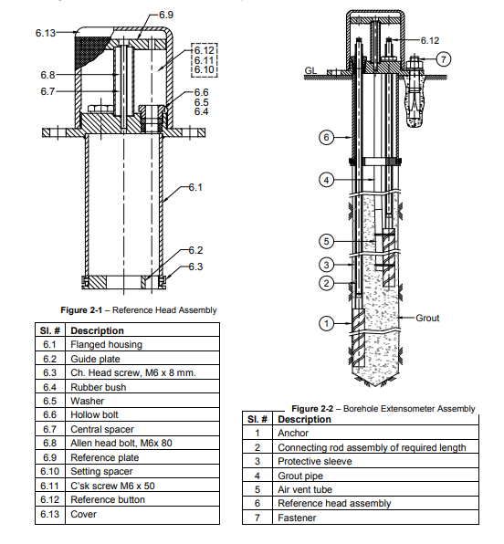
Mechanical Borehole extensometer Model EDS-63UD measures the displacement taking place in a borehole concerning time. It helps to accurately measure the change in distance between various anchors and monitor GL their relative displacement with time. It is usually assumed that the deepest anchor is in the stable ground and so any change in anchor spacing is interpreted as sag of roof bed, movement of the sidewall or slope, settlement of the foundation, etc.
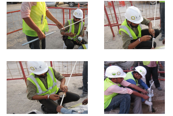
Procedure for extensometer installation with stainless steel connecting rod assembly.
- The first step of the extensometer installation is to sort out the components that are required for completing individual borehole extensometer assemblies in individual groups.
Our connecting rods are available in 1, 2, and 3 m lengths with an M6 x 12 mm male thread at one end and an M6 x 15 mm female thread at the other end.
To give you an example, in case the extensometer is 16 m long, it can be modeled with five connecting rods of 3 m and one connecting rod of 1 m length threaded to an anchor.
NOTE: A special fraction-length connecting rod is provided for borehole extensometer assembly that needs depth in a fraction of a meter.
NOTE: Encardio Rite measures the depth of the anchor as the distance from the mouth of the hole to the near end of the anchor.
- Extensometers are installed with the deepest anchor first and then to the shortest anchor. The longest connecting rod of the deepest extensometer is threaded to the anchor. Next, use Loctite 577 to seal the thread.
NOTE: To seal the connecting rod to the anchor, or to connect rod threads, always use Loctite 577 as a sealant.
- Cut a PVC Rigid pipe at least 3m long by 150 mm from the plain end. The opposite end contains a socket which is used to connect to the next PVC pipe. Place this 2.85m long PVC pipe on the connecting rod and use Loctite 577 to fix it to the end of the anchor. Use Mahendra’s M-seal compound to give it a good fix, in case the PVC pipe is loose over the anchor end. Make sure the PVC pipe is firm and robust since we don’t want any grout escaping from it.
NOTE: The joint between the PVC pipe and anchor should be sealed completely to prevent any grout leakage.
- A flexible PVC grout tube of 30 kg/cm2 burst pressure rating (12.5 mm bore x 2 mm wall thickness) around 2 m longer than the length of the deepest anchor is used for this step. Use the PVC tube and fix it with rubber bands or tape to the anchor in a manner that it is around 50 mm beyond the far end of the anchor.
Also Read: Borehole Extensometer Installation Procedure with Fibreglass Rod Assembly
NOTE: Make sure the PVC tube is lightly gripped to the anchor as the tubing is withdrawn as the grout is filled.
- Cautiously push the anchor, PVC pipe assembly, connecting rod, and grout pipe inside the borehole.
- Use Loctite 577 to thread another connecting rod of the required length. Continue doing so until all the connecting rods are assembled while being attentive that they are properly enclosed with PVC protective rigid pipe.
- Use any PVC jointing compound or Loctite 577 to seal PVC to the PVC pipe. When you reach the last connecting rod, make sure that the overall length of the PVC tubing is 150 mm shorter than the length of the connecting rods.
- Use the rubber boot to slide over the connecting rod and then seal it over the PVC tubing face with Loctite 577. Make sure to leave the extensometer end around 300mm outside the face of the housing.
NOTE: Precaution should be taken during extensometer installation to ensure that the assembly is not dropped into the borehole accidentally. You can safety rope or clamps to secure the assembly.
Safety clamps are available from Encardio Rite. They have a groove that fits into the spanner slot on the connecting rod.
-
- Assemble the next longest anchor assembly using the same procedure as mentioned in Steps 3-7. Use the same steps for installing the other anchor assemblies.
- It is important to mark the connecting rods based on their depth. Use tape and paper, marking the deepest extensometer anchor assembly as “1”, and then 2, 3…and so on.
NOTE: For a vertical downhole, a grout tube with one end fixed to the deepest anchor is preferred. Tubing is drawn up from the borehole as grout is pumped in.
In some cases, a second shorter grout tube is used by fixing it to an anchor about halfway down the length of the extensometer. This is useful if placed where a longer tube possesses some difficulties.
- Secure the reference buttons to the connecting rod ends with the help of Loctite 577.
- Tighten setting rods to reference buttons, ensuring that you do not use any Loctite 577 in this case as they need to be removed at a later stage.
- Bind the mounting plate on the setting rods with M8 nuts and washers making sure that the grout pipe/pipes pass through the central hole of the mounting plate.
- Connect the flexible grout tubing to the grout pump and pump grout till the anchor closest to the mouth is fully covered with grout. Make sure the grout is never filled up to the mouth of the borehole.
- Remove the flexible grout tubing progressively from the hole as the grout fills in. Pump fresh water to clean the grout pipe/pipes for subsequent use. Leave the grout for 24 hours to let it set in.
Read More: Multipoint Borehole Extensometer- Introduction, Application, and System Requirements
NOTE: The reason why grout should not be filled to the mouth during extensometer installation is that there has to be some flexibility to position the connecting rods inside the housing. It also dismisses the possibility of grout flowing into the PVC protective pipe.
Grout should cover the anchor closest to the mouth or be around 1 m from the face of the borehole whichever distance is less.
- Remove the setting space and Insert C’sk screw M6 x 50 over the connecting rod extensions. Place it properly in the groove on the housing and secure the reference button to the housing with the three Allen head bolts provided.
- Remove the setting rods. If they do not come out easily, use two M8 nuts together on the threaded portion and remove them with a spanner.
- Align the holes between the reference plate and button, and use an Allen head bolt to assemble a reference plate to the reference button
- Mark the side of the housing using permanent markers.
- Make use of the depth micrometer (least count 0.01 mm) to take the initial depth reading of the reference buttons from the reference plate. These will form the reference readings. The difference between these readings from any subsequent readings will give the deformation.
NOTE: If the extensometer installation is done accurately, the depth of the reference button from the reference plate at the time of initial reading will be around 125 mm.
- Secure the cover over housing. In case of any damage to the assembly due to construction activity or vandalism, provide additional protection as per requirement.
This brings us to the end of the extensometer installation with stainless steel connecting rod assembly. I hope you found this helpful. If you’ve any doubts or questions, feel free to comment below.