Encardio Rite Borehole Extensometer with Vibrating Wire is used to measure the extension (displacement) that takes place with time in a bored hole or several bored holes in a rock mass.
We will be looking at the Vibrating Wire Extensometer Installation Procedure in this article.
It consists of one or more anchors and a reference plate. Anchors or anchors are set in the same borehole or different boreholes drilled adjacent to the first borehole. The extensometer helps to accurately measure the distance between various anchors concerning the reference plate and thus monitor their with time their relative displacement.
Tools and accessories required for installation
The following tools and accessories are necessary for the vibrating wire extensometer installation procedure:
- Soldering iron 25 watt
- Rosin 63/37 solder wire
- Thread sealant (Loctite 577 or equivalent)
- Cable jointing compound
- Acetone (commercial)
- Spanner 6, 8, 10, 18, 24, 30 and 38
- Allen key 2, 4 3.4.8 Screwdriver (tip size 6 x 0.8 and 3 x 0.5 mm)
- Phillips head screwdriver (tip size 2 mm)
- Hacksaw with 150 mm blades
- Cable cutter
- Wire stripper
- Insulated pliers 165 mm
- 150 mm flat file
- Toothbrush
- wire brush
- Cloth for cleaning (lintless)
- Cello tape/Insulation tape
- Micrometer depth gage 100 mm range
- Digital indicator model EDI-54V
- Digital multi-meter
Vibrating Wire Extensometer Installation Procedure
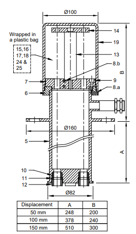
- Refer to the above image and remove the cover (19) to take out the polythene bag that contains a requisite quantity of reference buttons (15), link plates (16), sensor tightening nut (17), locknuts (18), M6 x 100 cheese head screw (24) and locking nuts (25).
- Remove guide plate (7) with the help of a 4mm Allen Key and hollow bolts marked 1, 2, and 3 from flanged housing (5). Place the housing on the clean ground, ensuring that it is at least 1m away from the borehole. Loosen the other two hollow bolts slightly from holes marked V and G.
- The next step in the vibrating wire extensometer installation procedure is to cut grout and air vent tubes (12 mm od x 10 mm ID supplied in coil form) to the length that is required. In most cases, the lower end of the grout tube is placed at a level higher than the anchor which is the closest to the face of the borehole. Make sure that the grout covers the anchor closest to the borehole mouth or is around 1 m from the face of the borehole, whichever is closest. When you’re determining the length of the grout tube, remember that around 1.5m of it is required to be outside the reference plate as it used to easily attach to the grout pump. Similarly, the air vent tube should project around 0.3 m outside the reference plate. As we did for the grout covers, the lower end of the air vent tube should always be at a higher level than the lower end of the grout tube. When it is time to insert the last anchor in the borehole, make sure the lowest end of the grout tube is tied to the connecting rod with a cable tie.
NOTE: 1. When installing upward to the horizontally sloping borehole, make sure the grout tube is 2m longer than the specified depth of the deepest anchor and taped around 100 mm below the far end of the anchor. To prevent it from swinging loose, use PVC tape and tape the grout tube every 2m to the plastic tube of the connecting rod assembly.
2. In an upward to horizontally sloping borehole, ensure that the air vent tube is 1.5 m longer than the specified depth of the deepest anchor and taped around 100 mm above the far end of the anchor. Similarly to what we discussed above, tape the air vent tube with PVC tape at every 2m to the nylon tube of the connecting rod assembly. Top-end of the air vent tube should be at a level higher than the deepest anchor.
CAUTION: When installing the upward to the horizontally sloping borehole, attention should be paid to make sure that the air vent tube is taped around 100 mm beyond the rear of the deepest anchor and does not get detached. This is very necessary for the grout to fill in up to the end of the longest anchor.
- Take the grout tube through the hollow both (12) of the hole marked G at the bottom of the flanged housing and corresponding holes on guide plate (7) and reference plate (14), taking care that when the flanged housing is assembled to the adaptor (6), the grout tube is around 1.5 m outside the reference plate. Similarly, guide the air vent tube by a hollow both of the holes marked V at the bottom of the flanged housing ensuring that when the flanged housing is assembled to the adaptor (6), the vent tube is around 0.3 m outside the reference plate (14).
- Use a spanner of size 18mm to tighten the corresponding hollow bolt (12) which will securely hold the nylon grout and the air event tubes but not so tight that it squeezes them.
CAUTION: In upward to the horizontally sloping borehole, be particularly careful in tightening the hollow bolts (12) properly as grout may leak through into the reference head assembly during the grouting process. - The next step is the vibrating wire extensometer installation procedure involves replacing the hollow bolts (12) in holes marked 1, 2, and 3 on the flanged housing loosely tightening them with the hand.
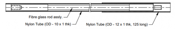
- Fix the male end of the connector of the longest fiberglass assembly (2) to the routable anchor(1) by screwing it in. During the fixing, the nylon tubing will also get tightly gripped to a groutable anchor. You may need a little grease for ease in assembly.
- The next step is to place the deepest groutable anchor in the borehole until 1.5m of the near end of the fiberglass rod is outside the face of the borehole. Trim the nylon sleeve such that the female connector and fiberglass rod are exposed by around 100 mm from the connector end.
WARNING: Fibreglass rod is supplied in coil form using cable ties. Make sure you’re very careful while handling it as it can unwind and snap back.
- Guide the end of the fiberglass rod through a hollow bolt (12) of the hole marked ‘1’ at the bottom of the flanged housing (5) and corresponding holes on the guide plate (7) with the end protruding around 80 mm from the guide plate (7) face. For this process, the fiberglass rod will have to be bent. Tighten the hollow bolt-on connecting rod such that it does not slip into the borehole.
- Repeat the above 2 steps of the vibrating wire extensometer installation procedure for the second deepest anchor and guide the connecting rod end through a hole marked ‘2’ at the bottom of the flanged housing (5). Follow the same procedure for the near anchor.
NOTE: 1. When Installing the extensometer, always start by assembling and mounting the deepest anchor first. It is a good practice to avoid confusion at a later date in the identification of anchors. Holes on top of flanged housing are marked clockwise with identification numbers 1, 2, 3, and G respectively, and V in the middle.
2. While installing the extensometer on a sidewall of the roof, it is generally expected to use an extension. In such a case, it is recommended to place the connecting rod end as close as possible to the reference plate (14).
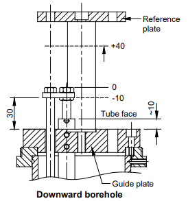
Similarly, in the case of vertically down borehole settlement, it is advisable to set the connecting rod end as close as possible to the guide plate (7). In other cases, it may be necessary to set the connecting rod end in the middle such that either compression or tension can be monitored.
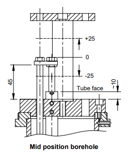
In other words, if only the compression is expected, set the zero reading of the sensor by extending the shaft by around 10 mm. If you’re expecting only the extension, set the zero reading of the sensor by extending the shaft by around 10 mm less than the sensor range. You also set the sensor in mid-position if required but make sure never to set the sensor at the very end. A set of 100 mm long cheese head screws (24) and locknuts (25) is provided for this purpose.
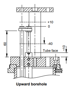
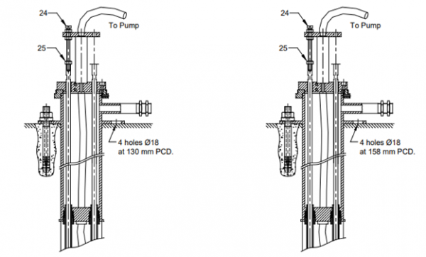
- Construct cheese head screw (24) and locking nuts (25) as shown in the figure below. Lightly loosen the hollow bolts (12) related to holes ‘1’, ‘2’ and ‘3’. Adjust the end of a connecting rod in the required position and tighten the locknuts (24).
NOTE: If EDI-54V shows a negative displacement reading, move the structure away from the borehole face and vice-versa.
- Re-assemble guide plate (7) to the adaptor (6) with Allen screws (9) taking care that holes marked ‘1’, ‘2’, ‘3’, ‘G’, and ‘V’ are aligned in reference plate (14), guide plate (7) and flange housing (5).
- Use a spanner size of 18mm to tighten the hollow bolts to secure the nylon tube but make sure you do not squeeze or restrict the free movement of the female end connector inside the nylon tube.
NOTE: When dealing with upward to the horizontally sloping borehole, tighten the hollow bolts (12) with attention and care as the grout may leak through into the reference head assembly during the grouting process.
NOTE: You have to take extra precautions to make sure the extensometer assembly does not drop into the borehole accidentally. It is advisable to secure it properly by attaching a safety rope to the anchor.
- The next step in the vibrating wire extensometer installation procedure is to soak rags or jute cloth strips in quick-setting cement water mix and wrap it outside the flanged housing (5) to build up an approximately 5 mm thick layer. Lift and insert housing in the borehole using a to and fro screwing motion sealing the annular space between housing and borehole.
- Secure the expandable anchors (21) in holes that were drilled before to bind the flanged housing with M16 nuts and washers which are provided. Allow the flanged housing to set in the borehole for some time.
- The next step in the vibrating wire extensometer installation procedure is to fix the grout pipe to the grouting machine and pump until the cavity is filled with grout and it overflows out of the air vent pipe. You should pay extra care to ensure that the grout flowing out of the air vent tube does not find its way into the flanged housing and disrupt the installation procedure.
- Pump clean water through the grout tube till clear water comes out of the air vent tube. This is done to keep the grout tube clean for topping up the grout later on. Allow the grout to settle in for some time.
NOTE: The cement water proportion depends upon the site conditions. Make sure to check with the engineer for the grout. The generally accepted and successful composition for hard rock is 50 kg of cement with 30 kg of water
NOTE: Make sure the grout covers the anchor closest to the mouth or is around 1 m from the face of the borehole, whichever distance is less. You can confirm this by inserting a 3 mm wire into the borehole through the vent pipe.
CAUTION: Take precautions to ensure that the grout does not overflow into the flanged housing as it may get into the protective nylon tubing and jam the setting rods.
- During the Vibrating Wire Extensometer installation procedure, ensure that all the anchors are securely and completely grouted, and pump the grout into the system again after the setting period of the grout is over. It may be that the heavier grout settles at the bottom, leaving the anchors near the face of the borehole in water instead of the grout. To ensure that this is not the case, pump the grout in again so that the water at the top is pumped out through the air vent tube and replaced by grout.
CAUTION: It is important to keep all the anchors properly grouted to get the correct displacement readings.
NOTE: For very deep holes, staged grouting may be necessary. It is recommended to take the advice of the grouting engineer at the site. If this is necessary, procure a Borehole Extensometer with provision for one extra connecting rod hole and use this hole for an extra grout tube.
NOTE: You don’t have to fully grout the borehole when using packer anchors. Use a hand grout for better control. Remember, when you have to saturate packer geotextile sufficiently, you should pump water first. When the pressure builds up to around 400 to 500 kPa, stop pumping the grout and wait for the pressure to dissipate. Once a few minutes have passed, pump again till you feel a distinct pressure. The recommended grout mixture is 1 part cement and 1 part water by weight. King and tape the grout tube to maintain the pressure and disconnect the pump. Clean the pump thoroughly once the above steps are done.
- The next step in the vibrating wire extensometer installation procedure involves removing a lot of parts. Remove screws (24), locknuts (25), reference plates (14), and spacers. To remove the grout and vent tubes, you will need to cut. Once they are extracted, round edges of the grout and vent tube with a hand file. While cleaning the reference head assembly, make sure you do it in a detailed manner. Reassemble the reference plate with spacers to the guide plate.
- Remove the guide plate assembly from the adaptor (6).
- Keeping in mind that the cable has to ultimately connect to the junction box, embed the first sensor in the flanged housing. Using grub screws, fasten the sensor to the guide plate, guaranteeing that 10mm of the tube face is outside the face of the guide plate.
- Pull the shaft of the sensor and assemble it to the connecting rod end with reference button (15), link plate (16), sensor tightening nut (17), and locknut (18).
- Secure the sensors by screwing them to their respective connecting rods keeping in mind the position of extensometer “1”.
CAUTION: Make sure to never rotate the shaft of the displacement sensor concerning the outside body as it can permanently damage the sensor. Carefully pull or push the shaft only axially when installing the instrument. A pin has been provided at the end of the displacement sensor that sits flush in a groove in the sensor body. Make sure you keep the pin seated inside the groove during assembly operation and tighten it such that no force is exercised on its shaft and there is no rotational movement.
CAUTION: You may need to replace the thread used while mounting the sensor. Make sure you don’t use the thread sealant as it may be difficult to remove them later on.
- Using the Encardio Rite Readout unit, measure the displacement of the sensor. Reading at this stage should be around the initial reading. To set the reading precisely, lose the respective sensor with grub screws (8) and reposition the sensor in the guide plate and tighten the grub screws again.
- Set your reading to zero in the Model EDI-54V to set the position of the sensor. Subsequent readings will determine the relative displacement between anchors.
- Use a micrometer to note down the initial reading. Make sure you also record the date, time, and temperature while taking the initial reading.
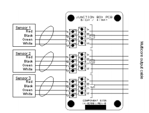
- Connect the nipple (22) to the socket of flanged housing and attach the junction box assembly (23) to the cables from sensors routed to the junction box.
- Connect leads to respective connector pins in the junction box.
- Replace cover (19) over guide plate (7).