The vibrating Wire Piezometer is designed to measure pore water pressure in the soil, earth/rock-fill foundations, and concrete structures.
Measurement of pore water pressure is used to detect the level and flow pattern of groundwater. It is also used to determine the flow pattern of water in earth/rock fill & concrete dams and the load-bearing capacity of soil or rock.
The vibrating wire piezometer installation procedure requires complete knowledge and assistance. Let us see how it is installed in a borehole. Before diving into that, we recommend you to go through the How Is Vibrating Wire Piezometer Installation Done?
Once you have prepared the piezometer for installation, you can proceed further.
How to Install a Vibrating Wire Piezometer in a Borehole?
The vibrating Wire Piezometer is installed in a borehole using a fully grouted method. Using a traditional method involves the placement of sand pockets surrounding the piezometers, grout columns, and bentonite seals to separate piezometers at different levels. It is a slow and complicated process which also poses a great risk of unintended communication between piezometers.
On the other hand, the fully grouted method is quick and simple, resulting in excellent zone isolation.
Vibrating Wire Piezometer requires a very small volume of water to read a change in pore water pressure, thus resulting in a fast response time.
- The first step is to ascertain the installation depths of the multilevel piezometers. The cable connected to the piezometer should have a required length of the installation depth plus an extra length of 1 to 2 m.
- Locate the precise location of the borehole by surveying, to determine where the borehole/foundation piezometers are to be installed.
- Using Guargum as a drilling method, drill a hole of 100mm diameter to a depth of around 1 m below the elevation at which the piezometer is to be installed. If needed, use casing to prevent the sidewall of the borehole from collapsing. Make sure to wash the borehole clean, top to bottom, by pumping in freshwater.
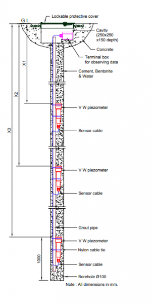
- The next step is to connect the bottom-most piezometer to the sacrificial grout pipe about 300 to 500mm from the end. For sacrificial grout pipe, a 20mm, bell-ended or threaded, PVC pipe can be used.
- Use a nylon cable tie to attach the piezometer, with its tip pointing upwards to the PVC pipe. This is done to prevent the leakage of de-aired water confined between the diaphragm and filter and also to reduce the possibility of de-saturation.
NOTE: Encardio Rite Model EPP-30V is recommended for long-term monitoring. A smaller diameter borehole can be drilled for EPP-40V as its outer diameter is 19mm.
Also Read: Vibrating Wire Piezometer – Types and Operating Principle
- To take the reading in frequency, connect leads to the readout unit EDI-51V. The reading displayed is said to be the “initial reading” that is entered into the EDI-51V for the sensor to set up. To record the ambient temperature, shift the mode to “temperature”.
- After following the above steps, it is time to lower the assembled instrument into the borehole. Using a nylon cable tie or BOPP tape, attach the cable from the piezometer to the grout pipe at nearly the same intervals. Use the same method to attach subsequent lengths of grout pipe. The cable should be taped above the grout pipe at regular intervals. The borehole should be held at the top in such a way that there is a gap between the grout pipe and the borehole bottom.
- Once the complete assembly is lowered down the borehole, take readings of the piezometer to check the function. The reading should be in line with the height of the water column above the piezometer.
- To fill the annular space between the piezometer assembly and borehole, prepare a grout mix as instructed by project authorities. If no instruction is given, prepare the grout mix as mentioned below:
Cement 50 kg
Bentonite 15 kg
Water 125 liters.
NOTE: Make sure to prepare the grout mix in an adequate amount so that the continuous grouting of the borehole can be carried out without choking the borehole and loss of instrumentation.
- Here’s how you prepare a grout mix. The first step is to mix cement in water. Slowly add bentonite in the cement-water mix such that the clumps are not formed. Once the mixture turns into an oily/slimy consistency, stop adding the bentonite. After mixing the grout for 5-10 minutes, check the consistency. Add more bentonite, if needed, to make the grout as consistent as cream. Make sure it is not very thick as that would make it difficult to pump into the borehole.
NOTE: Before lowering the piezometer in the borehole, record an initial reading and temperature with EDI-51V for a permanent record. This will form the zero reading for the piezometer. Also, note the barometric pressure at the time of taking an initial reading.
Also Read: What Are The Different Types Of Piezometers?
- Using the sacrificial grout pipe, Pump grout in the annular space between the borehole and piezometer until it reaches the ground surface. In case, a casing is used for preventing the borehole walls from collapsing, pull it out as the borehole is grouted.
NOTE: It is advised to keep the maximum discharge head capacity of the grouting pump (Trash Pump) higher than the maximum depth of the borehole. If no details are available, the suggested grout pump is as follows:
Model KTH-80X-BAB
Make Keshin Ltd.
Mix Discharge head 27 m
Delivery Volume 1340 l/min
- To settle the grout mix, leave it overnight or at least for 12 hr. The next day, top up the settled grout to the ground surface.
- After the borehole is grouted, take readings of the piezometer. The readings should ideally be more at this stage due to the grout column above the piezometers, which is denser than water. The grout takes at least 2 days to cure and the readings normalize as the grout cures.
- The next step is to make a 400 mm x 400 mm concrete platform on top and install a 250 mm x 250 mm lockable protective cover. After that, the cable ends in a terminal box for observing data, located in the niche/cavity.
NOTE: Specially treated piezometers are used for saline water applications. The stainless steel diaphragm is protected with a thin layer (around 1 mm) of GE Silicones compound TSE 399. The remaining exposed cylindrical surface of the piezometer stainless steel body should be wrapped by saline-resistant tape like “33 super PVC 3M tape”. Particular care should be taken to cover the joint between the piezometer and the cable joint housing.
NOTE: At certain locations like earth/rockfill or concrete dams, it is convenient not to have the junction box and route one continuous cable from the sensor to the observation room. In such a case the platform (clause 4.3.13) is not made.
NOTE: Make a note of the elevation at which the piezometer is installed for future correlation of data and its analysis.
Here we come to an end of the vibrating wire piezometer installation procedure in a borehole. We hope you might have found this useful. If you have any questions or suggestions, feel free to drop them in the comments below.