A vibrating wire piezometer is used to measure pore water pressure in the soil, earth/rock-fill foundations, and concrete structures.
Vibrating wire piezometer finds its applications in the measurement of positive or negative pore pressure in the soil, concrete mass, or rock which also includes:
- Construction control, stability investigation, and monitoring of earth dams, embankments, foundations, shallow underground works, and surface excavations.
- Uplift and pore pressure gradients in foundations, embankments, abutments, and fills.
- The hydrological investigation, groundwater elevation study, and water supply operations.
- Waste and environmental applications
- Soil improvement & stability and slope stability
Vibrating Wire Piezometer: Operating Principle
The vibrating wire piezometer is made up of a magnetic, high tensile strength, stretched wire. One end of this wire is anchored or attached, while the other end is secured to a diaphragm that deflects in some proportion to the applied pressure. The diaphragm is deflected proportionally, with the change in the pressure which, in turn, affects the tension in the wire.
Therefore, as soon as there is any change in the pore water pressure, it is reflected in the tension of the stretched wire.
The high-tensile strength wire is plucked by a coil magnet and resonates at a frequency proportional to the tension in the wire. The frequency can be measured as:
f = [σg/ρ] 1/2/ 2l Hz where;
σ = tension of the wire
g = gravitational constant
ρ = density of the wire
l = length of wire.
The frequency resonated by the wire leads to an alternating current in the coil magnet. The pore pressure is measured as being proportional to the square of the frequency and the Encardio Rite model EDI-51V readout logger displays this directly in engineering units.
What is a Vibrating Wire Piezometer?
Piezometers are available in various capacities that are used in specific conditions. A thermistor is present in all kinds of piezometers which monitors temperature and may even make a temperature correction in the zero reading. (Discussed Later)
There is also a tri-polar plasma surge arrestor present inside the transducer housing that protects the vibrating wire pluck and read coils from electrical transients that may be induced by direct or indirect lightning strikes.
Types of Encardio Rite’s Vibrating Wire Piezometers
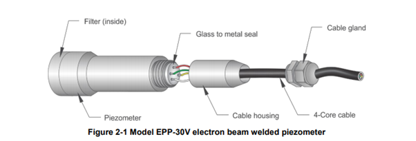
Model EPP-30V Electron Beam Welded Heavy Duty Piezometer
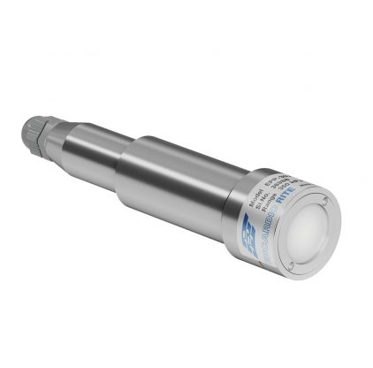
Model EPP-30V Piezometer
Encardio Rite’s Model EPP-30V Piezometer has the vibrating wire and coil magnet protected in a stainless steel body which, in turn, is an electron beam welded to the diaphragm. This creates a vacuum of 1/1000 Torr inside the sensor, making it immune to the effect of water which may enter, or any other corrosive materials. The stainless steel construction protects the piezometer from chemical corrosion which may happen at any of the locations where the piezometer is used.
The Model EPP-30V electron beam welded heavy-duty piezometer is provided with a low air entry value ceramic flat filter which has a thickness of 3 mm and a grain size of 40-60 microns. The water that leaks through internal pores or seams in rock formations of dam foundations, mass concrete of structures, foundation soil of structures, reclaimed land soil, etc., finds its way to pressurize the diaphragm through the filter. Throughout the entire process, the filter is held in its place by a locking nut.
epp-30v electron beam welded piezometer
The locking nut can be reassembled by a bent nose plier which is provided with the product. The locking nut is usually removed to fill up the cavity behind the filter with de-aired water or to saturate the filter with water.
The wires from the coil magnet end on the glass to metal seal which is integrally electron beam welded to the stainless steel body of the piezometer.
The coil magnet is connected to the pins marked as red and black whereas, the other two pins are connected to a thermistor. The cable connection is maintained by a cable joint housing and cable gland.
Model EPP-40V Slim Size Vibrating Wire Piezometer
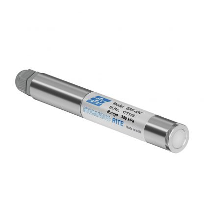
The Slim Size 19 mm φ Piezometer is usually used for monitoring pore pressure in boreholes during construction operations. Alike Model EPP 30 V, the slim-size piezometer is an electron beam welded with a vacuum of around 1/1000 Torr inside it. The product also has a low air entry value ceramic flat filter with a grain size of 40-60 microns along with a cable joining the glass to metal seal like the previous Model.
The Slim Size 19 mm φ Piezometer is usually used for monitoring pore pressure in boreholes during construction operations. Alike Model EPP 30 V, the slim-size piezometer is an electron beam welded with a vacuum of around 1/1000 Torr inside it.
The product also has a low air entry value ceramic flat filter with a grain size of 40-60 microns along with a cable joining the glass to metal seal like the previous Model.
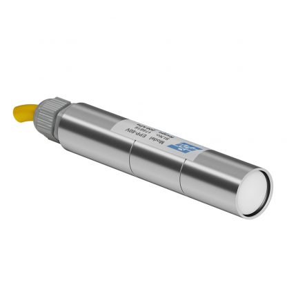
Model EPP-60V Low-pressure Piezometer
epp-60v vibrating wire piezometer
As the name suggests, the Model EPP-60V Piezometer is used to measure low water pressure.
The Model is crafted with a basic pressure sensor of 30 mm diameter which is suitable to measure water level and pressure in boreholes.
However, the pressure sensor is applicable where the maximum hydrostatic head (height of water level above piezometer location) is less than 7 m over the sensor diaphragm.
Model EPP-50V Push-in Vibrating Wire Piezometer
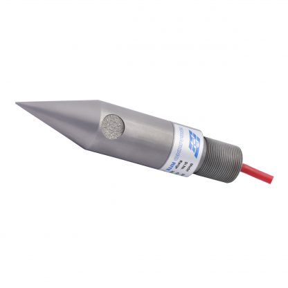
epp-50v vibrating wire piezometer
The Push-in Piezometer is specifically used to monitor pore water pressure in soft soil/clay and landfills. Designed with a pointed cone at one end and drill rod threads at another end, the piezometer is inserted into the borehole, threaded into a drill rod, and then thrust into the soft soil directly.
The cable wire of the Push-in piezometer is passed through the drill rod. It is provided with a standard 1 m long polyurethane sheathed cable which is expandable as per the requirement with a kit. However, if specifically requested, the piezometers are supplied with the requisite length of cable attached.
| Also Read: Piezometers: Types, Functions, & How it Works? |
What is a Zero Reading?
The Encardio Rite Vibrating wire piezometer is designed in such a way that even when there is no pressure on the diaphragm, the wire vibrates at an initial frequency. This would imply that even with zero pressure, there would be some initial frequency reading.
Therefore, it is important to determine the zero reading as accurately as possible, because, the reading will be used for subsequent data reduction.
However, five Special considerations should be taken into account:
- The piezometer temperature must reach thermal equilibrium. Temperature varies across the body of the piezometer which results in reading errors. Piezometers need 20-25 minutes to stabilize their temperature provided that sunlight does not fall on any surface. Borehole installation works slightly differently. The piezometer is lowered into the borehole, stopping just above the water table. The piezometer is allowed to reach thermal stability before doing its function.
- Make sure that the filter is completely saturated with water as the reading can be severely affected because of the surface tension effects in the pores of the filter. The problem becomes more grave at pressures below 0.5 kg/cm2
- It is advisable to remove the filter while conducting any preliminary tests which may involve raising or lowering the piezometer into a fluid-filled borehole,
- Make sure that the temperature and barometric pressure are recorded at the time of taking zero readings.
- When the piezometer and cable are lowered into a borehole, there is significant displacement of the water column which affects the water level reading. It is important to allow sufficient time for the water level to stabilize while monitoring the level in a standpipe.
How to take readings with a vibrating wire indicator?
Model EDI-51V Vibrating Wire Indicator is a microprocessor-based readout unit designed for the use and measurement of Encardio Rite’s range of vibrating wire transducers.
The EDI-51V displays the measured frequency in terms of the period, frequency squared, or the value of the measured parameter directly in proper engineering units. It can also store calibration coefficients of up to 500 vibrating wire transducers which allow the values to be presented in proper engineering units.
The Vibrating Wire Indicator has an internal non-volatile memory that can be used to store 4,500 readings from any of the 500 programmed transducers in any combination. 4,500 sets of readings can be stored either from any transducer or 9 sets stored from all 500 transducers. To keep a measured record, each reading is imprinted with the date and time of the measurement.
Individual “Test Certificate” is provided with each transducer where the Calibration coefficients are given. The gage factor is given in the test certificate and the zero reading in frequency2 (digits) at the time of installation is used for setting up the transducer coefficients in the readout unit.
For polynomial linearity correction, the Test certificate provides a factory zero reading in frequency2.
Polynomial linearity correction uses a formula for the pressure which is calculated by the following equation:
P = A (R1)² + B(R1)² + C (MPa) where
P = pressure in the engineering unit
R1 = current reading in digits during observation
A, B, C = polynomial constants
The polynomial constants are stored in model EDI-51V memory to give linearity-corrected data of the parameter in engineering units.
The model EDI-51V vibrating wire indicator also displays and records the temperature of the transducer directly in degrees Centigrade, for transducers with a built-in interchangeable thermistor. Except for the temperature sensor, every Encardio Rite vibrating wire sensor has a thermistor included in it for temperature measurement, unless the customer does not require it.
The stored readings are preserved by either uploading to a host computer or printing it out on any text printer equipped with an RS-232C serial communications interface. The set-up information (calibration coefficients) for all the channels can also be printed out for verification. An internal 6 V rechargeable sealed maintenance-free battery is used to power the readout indicator.
A separate battery charger is provided with the EDI-51V indicator to charge the internal battery from 230 V AC mains. The EDI-51V indicator is housed in a splash-proof resin molded enclosure with weather-proof connectors for making connections to the vibrating wire transducer and the battery charger.
This was all about the general principle and types of piezometers. If you have a query or suggestions to make, feel free to drop them in the comments section below.