The borehole extensometer Model EDS-63U/D is commonly used for the upward or downward-sloping hole with the help of fibreglass connecting rods or stainless steel extension rods. Making use of the EDS-63U/D system, up to three extensometers can be installed in a borehole of φ 76 mm with a diameter at the mouth of the borehole increased to 90 mm up to a depth of 200 mm. Up to six extensometers can be installed in a borehole of φ 102 mm with a diameter at the mouth of the borehole increased to 125 mm to a depth of 225 mm.
Multipoint Borehole Extensometer-Application
Let’s see where we find the Multipoint Borehole Extensometer useful.
- To learn the behaviour of the roof or wall of a mine, tunnel, or underground cavity during an excavation.
- To examine the effectiveness of the roof/wall support system of a mine, underground cavity, or tunnel.
- It used to be a step ahead of accidents by predicting the potential roof or wall fall before it happens. This is detected as the fall is invariably preceded by measurable sags as the strata open up, and the movement usually occurs at an increasing rate as fall conditions are approached. If the roof or wall fall goes undetected, it may result in serious accidents or may require costly patch-up and repair operations.
- To observe and measure the movements in slopes and foundations that occur due to the excavation of underground cavities or due to the construction of heavy structures like concrete, rock fill, masonry, or earth dams over the foundation.
Measurement method and anchors- Multipoint Borehole Extensometer
The measurement method used for the multipoint borehole extensometer is a micrometer depth gauge. As for the anchors, Encardio-rite presents two types of anchors. Let’s have a look at them:
The first type is a groutable anchor with a length of φ 20 mm x 500 mm, especially used for hard rocks. These anchors are connected to a rod of appropriate length, pushed in a borehole, and fixed in position by cement grout. The connecting rod is shielded from the cement grout as it is enclosed in nylon tubing. These anchors can be installed in vertical boreholes or upward inclined holes. However, in the case of holes inclined upward, special precautions are needed to retain and prevent the grout from flowing out of the borehole.
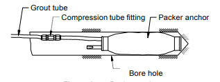
The other type of anchors, known as packer anchors, are used for soft rocks and soil. Similar to the groutable anchor, they are lowered into the borehole along with a connecting rod and fixed in position by pumping cement grout into the packer to take a firm grip on the surroundings.
Multipoint Borehole Extensometer- The explanation
The multipoint borehole extensometer finds its application in measuring displacement taking place in the borehole over time. It helps to precisely determine the change in distance between various anchors with respect to the reference plate (6.9) and monitor their relative displacement with time.
It is typically assumed that the deepest anchor is in the stable ground and hence any change in anchor spacing is described as sag of roof bed, settlement of the foundation, movement of sidewall or slope, etc.
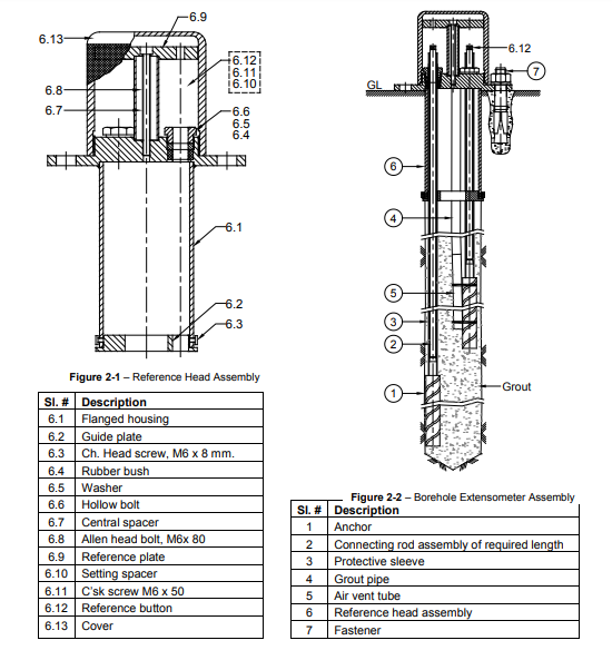
Multipoint Borehole Extensometer- The System Description
Encardio Rite Model EDS 63U/D is a piece of equipment in which up to six anchors can be mounted in a borehole and their relative displacement is monitored with time to a reference plate. In case access to the mouth of the borehole is easily available, mechanical measurement of displacement by EDS-63U/D is economical and reliable.
Using the micrometer depth gauge, the displacement reading is taken by measuring the depth of the reference button at the near end of the connecting rod from a reference plate.
All in all, the Multipoint Borehole Extensometer consists of three major systems-
- Reference head assembly
- Fibreglass assembly
- Anchor
Reference head assembly
For up to 6 extensometers, reference head assembly is installed in a borehole of φ 102 mm. The diameter at the mouth of the borehole is increased to 125 mm up to a depth of 225 mm. The flange has four 18 mm diameter mounting holes at a PCD of 158 mm. If less than six points are required other points are plugged with the help of a standard rubber plug, steel washer, and hollow hex bolts. (Refer to the images above)
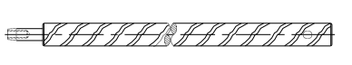
Fibreglass rod assembly
The fibreglass rod assembly consists of a fibreglass rod of a decided length shielded inside a continuous outer nylon tube. The rod has two end connectors. One end connector comprises of the male thread and is fitted into the anchor. The other end connected has a female thread used for the reference button.
As it should be, the anchor end is securely sealed with the anchor to block any grout from leaking in. The other end of the nylon tube is firmly sealed in the reference head assembly (refer to 6.4–6.6 in the figure above).
Proper care should be taken to firm seal in the reference head assembly especially for upwards to horizontally slanting holes as there is always a risk of the grout leaking into the reference head assembly during grouting.
The outer nylon tube allows free movement to the fibreglass rod and reference button even after the borehole is grouted.
NOTE:
Fibreglass rods are more proper for vertical upward holes rather than downward holes. The reason for this is that in vertically upward holes the rod is in tension whereas, in downward holes, it is in compression, which results in sagging or buckling. The longer the extensometer, the greater may be the sagging or buckling.
On the other hand, the shorter the extensometer, the more reliable the accuracy of measurement of relative displacement between anchors.
In conclusion, you should use stainless steel connecting roads in deeper boreholes as they are more rigid.
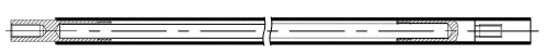
Stainless steel AISI 410 connecting rod assembly
Stainless steel AISI 410 connecting rods of 8 mm diameter are available in standard lengths of 1m, 2 m, and 3 m equipped with an M6 x 12 mm male thread at one end and an M6 x 15 mm female thread at another end.
These are attached at the site for positioning the anchor at the correct depth from the mouth of the borehole. To securely grip the connecting rods to each other, thread sealant Loctite 577 or equivalent is used between threads.
For example, in case the depth of a particular anchor from the mouth is 14 m, use four connecting rods of 3 m length and one of 2 m length. Similarly, in case the depth of the anchor from the mouth is 25 m, use eight connecting rods of 3 m in length and one connecting rod of 1 m.
A standard 14 cm spacer with male thread on one side and female on the other side is provided on the near end of the assembled connecting rods.
On the female end of this spacer, the reference button (6.12) is threaded. The male thread of the bottom-most connecting rod (most distant from the mouth of the borehole) fits into the anchor (1).
To enclose the connecting rods at the time of assembly, PVC tubing 14 mm ID x 10 mm ID in 3 m length is provided. One end of these tubes is swaged to form a male extender such that male and female ends of successive PVC tubes can be conveniently assembled using any PVC jointing compound in between. Once the jointing is done, double-check by pulling and then seal it with PVC tape to make it leakproof. The outer PVC tubing enables free movement to connect rods and reference buttons even after the borehole is grouted.
To prevent any grout from leaking in, the farthest PVC tubing from the mouth of the borehole is secured to the anchor. This 3 m long PVC tubing is cut by 50 mm from the plain end to make it accessible for successive connecting rods and PVC tubing to be connected.
The near end of the PVC tubing is firmly sealed in a flanged housing (6.1) with the help of a rubber bush (6.4), washer (6.5), and hollow bolt (6.6). The PVC tube should be cut such that when sealed in flanged housing, its face extends around 20 mm beyond the rubber bush (6.4). Proper sealing in reference head assembly is especially necessary for upwards to horizontally slanting holes to prevent any grout from leaking into the reference head assembly during grouting.