The digital inclinometers determine and measure the lateral movement in and around landslides, unstable slopes, landfills, tunnels, slurry walls, sheet piling, piles, diaphragm walls, and dams.
However, before installing a digital inclinometer, the placing of the ABS casing is the first step. Here’s how the digital inclinometer installation takes place in a diaphragm wall or pile.
Right before you start reading about inclinometer installation in a diaphragm wall, you should also go through:
Digital Inclinometer System: Preparing for Installation
How to Install a Digital Inclinometer in a Borehole?
Preparation for inclinometer installation in D-wall
It becomes a little problematic to install an inclinometer casing in a diaphragm wall or a pile. The inclinometer casing gets distorted and stressed when firmly tied to a steel structure from bottom to top. The heat of hydration and stresses generated during the concreting process may distort and even crack the casing.
1) The first step is to fix a 150 mm-bore diameter steel guide pipe vertically within the reinforced bar cage. The length of the pipe to be installed should be such that its top remains approximately 0.5 m above the current ground level. The bottom of the guide pipe should be around 0.5 m above the bottom level of the cage and sealed at the bottom with a concrete plug/plastic cap.
2) While the cage is being concreted, you need to make sure that the jointing of tube lengths is waterproof to prevent any grout/concrete from entering into it. Dented or distorted pipes should not be used as this will make installation of an inclinometer access tube difficult or even impossible.
3) We recommend installing an auxiliary guide pipe adjacent to the main guide pipe at 1.25 m approximately center-to-center distance at critical monitoring locations. This auxiliary pipe can be used in case the main pipe is choked and becomes useless.
4) Weld the guide pipe firmly to the cage. You need to ensure that it remains vertical and is least distorted during the lowering of the cage.
5) Concrete cage after covering the mouth of the guide pipe.
6) Flush the guide pipe clean with water and verify depth with the help of a suitable depth measuring device (e.g. a sounding chain) that it is fully open up to the bottom.
7) Before installing the access casing in the guide pipe, ensure that the heat of hydration of mass concrete has dissipated. You can use a temperature probe for this purpose. The temperature should not exceed 40 degrees Celsius. The heat of hydration, if present may warp access casing and render installation useless.
| Also Read Digital Inclinometer System: Introduction & How Does It Work |
Installation of inclinometer casing in MS casing (D-wall)
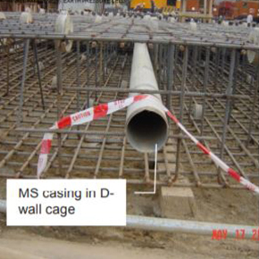
Figure 1
1) Lower the casing with the bottom cap into the guide pipe, gripping it with the safety clamp secured around 500 mm from the top. Maintain one pair of casing grooves parallel to the direction in which lateral movement is to be measured i.e. perpendicular to the diaphragm wall.
2) Take a casing pre-assembled with a fixed coupling, having a safety clamp secured around 500 mm from its top end, and mate it with the pipe, already lowered through the coupling end. Pop-rivet the fixed coupling to the lowered casing at four places.
3) Seal joint with mastic waterproof tape and BOPP tape
4) Remove the safety clamp from the first casing and lower jointed casings into the guide pipe. To counteract buoyancy, if required fill the casing with clean water to lower it into the guide pipe.
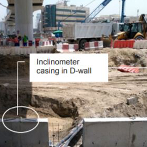
Figure 2
5) Repeat the above procedure for all the casings to be installed in the guide pipe.
Grouting in MS casing (D-wall)
1) Prepare a grout mix to be filled in the annular space between the guide pipe and casings as directed by project authorities.
If no instructions are available, the suggested grout mix is as follows:
Cement 50 kg
Bentonite 10 kg
Water 75 litres
2) It is recommended to flush the inside of the casing with water after grouting. This is to prevent any leaked-in grout from sticking to the casing and impairing the movement of the probe.
Top cover
1) The top of the uppermost casing should be 25 mm above the top of the steel pipe. Cut the top of the pipe suitably with a hacksaw. Use a flat file to make the pipe end smooth.
2) The depth of the top of the grout face from the top of the steel casing should be at least 100 mm (125 mm from the ABS casing top) as shown in Figure 3. This is necessary for fixing pipe extension jig over casing for taking readings.
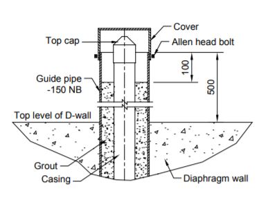
Figure 3
3) Clean the exposed portion of the casing top and fix the top cap.
4) The gage well should be protected with a cover fixed to the top of the steel casing by four M6 Allen head bolts, when not taking readings (figure 3).
Inclinometer Casing: After installation checks
1) Check the installed guide pipe for proper installation before installation of the access tubing. Ensure that it is sufficiently vertical and is least distorted.
2) Check the installed access tubing by dummy probe (EAN-26/2.2) before lowering the inclinometer probe.
3) Ensure fixing the protection cover and placing the top cap after the installation of the inclinometer casing.
Marking of grooves (sign convention)
1) Mark tag no. of installation in the paint on the inner side of the steel guide pipe. Also mark the casing grooves as ‘A+’, ’A-’,’ B+’, and ‘B-’ with a permanent ink marker pen. If the uppermost probe wheel is pointed in the direction of the major principle plane of movement, the casing groove pointing in this direction is marked as ‘A+’. Looking down the well, directions ‘B+’, ’A-’, and ‘B-’ are clockwise from ‘A’.
2) Plying of heavy machinery such as cranes, loaded trucks, etc. over the installation should not be allowed and, if required, proper fencing with warning flags should be provided. If necessary, the guide pipe with inclinometer casing should be cut short to just above the diaphragm wall top level and a lockable hinged cover should be provided. Readings can be taken using an extension jig.
Here we wrap up how the digital inclinometer installation procedure is done in a diaphragm wall or a pile. We hope you might have found this useful. If you have any questions or suggestions, feel free to drop them in the comments below.