A digital inclinometer system is used to measure the lateral movement and deformation of a structure. It provides information about the magnitude of inclination or tilt and its variation with time in structures like retaining/diaphragm walls, piles, etc.
The digital inclinometer installation procedure requires complete knowledge and assistance. Let us see how it is installed in a borehole. Before diving into that, we recommend you go through the Digital Inclinometer System: Preparing for Installation.
Once you have prepared the inclinometer for installation, you can proceed further.
How to Install a Digital Inclinometer in a Borehole?
Borehole Drilling
- Start by drilling a 125mm hole around 0.5m more than the planned depth of the inclinometer casing. (Try keeping the hole as vertical as possible)
- The diameter of the drill hole should facilitate grouting around the outside of the casing. A mobile rotary drilling rig using a rotary wash boring technique may be used to perform the drilling.
- The next step is to wash the borehole clean and verify that it is not blocked anywhere up to the bottom. To prevent the sidewalls of the borehole from collapsing, use a casing along with bentonite slurry.
Note:
If necessary, use suitable steel casing to prevent sidewalls of the borehole from collapsing. In such a case, steel casing will have to be gradually withdrawn as grout is pumped into the borehole.
In case spider magnets are used around the casing for settlement monitoring, the drill hole diameter should preferably be 150 mm.
Installing Inclinometer Casing in a Borehole
- Lower down the casing with the bottom cap into the borehole, gripping it with a safety clamp, secured around 500 mm from the top.
Note:
Maintain one pair of casing grooves perpendicular to the direction in which lateral movement is to be measured. If no such direction is known, maintain one set of grooves parallel to the N-S direction.
Take a casing pre-assembled with fixed coupling. Secure a safety clamp around 500 mm from its top end and mate coupling end with casing already lowered. Pop-rivet fixed coupling to the casing at four places.
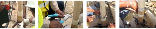
Figure 1: Inclinometer casing installation procedure
- Seal the joint with mastic waterproof tape and BOPP tape. Remove the safety clamp from the first casing and lower down the jointed casings into the guide pipe/borehole.
- To avoid buoyant force, fill the casing with clean water before lowering it into the guide pipe/borehole.
- Repeat the above procedure for all casings to be installed in a borehole.
| Also Read: Digital Inclinometer System: Introduction & How Does It Work |
Grouting in Borehole
Casings must be grouted as directed by project authorities. Ideally, grout should be mixed to match the strength and deformation characteristics of the material around the borehole. In practice, the main consideration is to use a grout that allows the casing to move with the surrounding material. For information, grout mixes used by some authorities are as follows:
Hard and medium soils
- Cement 50 kg
- Bentonite 15 kg
- Water 125 litres
28-day compressive strength was about 350 kPa.
Soft soil
- Cement 50 kg
- Bentonite 20 kg
- Water 325 litres
28-day compressive strength was about 30 kPa.
For mixing the grout, use a grout mixer or circulation method (figure 2), in case a mixer is not available. In the circulation method, a rig pump or a trash pump coupled to a gasoline engine (refer to Figure 1) is used for mixing the grout components i.e. water, cement, and bentonite.
Subsequently, the same pump can be used for pumping the grout to the bottom of the borehole. It is to be noted that pressure grouting is not required as the grout flows down under gravity.

Figure 2: Circulation grout pumping
Add cement to water first and mix. Add bentonite in small quantities slowly during the circulation process such that lumps of bentonite are not formed. Adjust the amount of bentonite to produce a grout within the consistency of heavy cream. If the grout is too thin, the solids and water will separate. If the grout is too thick, it will be difficult to pump.
Pull out and dismantle grout pipes one by one as the hole is being filled with grout.
For grouting the inclinometer casing in the borehole, the use of the tremie method is recommended (Figure 2). Lower down 20 mm nominal diameter rigid PVC pipe lengths, jointed using threaded sockets to around 0.5 m above the bottom of the borehole.
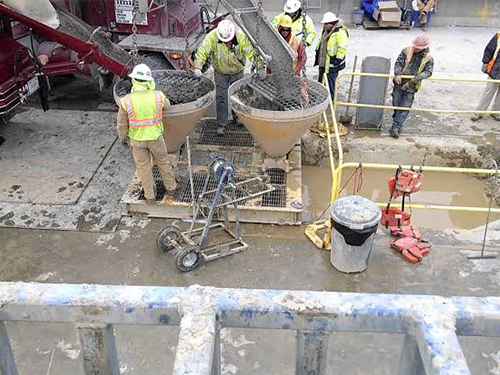
Figure 2: Tremie grout pumping
Fix the protective cover in the concrete platform on top of the borehole. Protective covers feature a universal key and dust protection for the lock (always put back dust protection after locking to avoid lock jamming). Typical dimensions for a concrete platform are given in Figure 3.
These may vary depending on local site conditions. The top of the uppermost casing should be kept below the final ground level and protected by a top cap and lockable manhole cover. Cut the top of the pipe suitably with a hacksaw. Use a flat file to make the pipe end smooth.
| Also Read: Inclinometer: Types, How It Works, & Uses |
After Installation Check
Check installed access tubing by dummy probe (EAN-26) for smooth movement up to the bottom of the borehole.
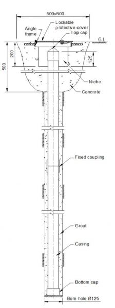
Figure 3: Checking Inclinometer casing after installation
Note:
The top of the uppermost casing should be 125 mm above the base of the niche as shown in Figure 3. The niche is around 200 mm deep. This is necessary for fixing pipe extension jig over casing for taking readings.
When not taking readings, gauge well should be protected by a top cap and the manhole cover should be kept locked.
Mark the tag number of the installation with paint on the inner side of the hinged cover.
Marking of grooves
Mark casing grooves as ‘A+’, ’B+’, ’A-’, and ‘B-’ with a permanent ink marker pen. If the uppermost probe wheel is pointed in the direction of the major principle plane of movement, the casing groove pointing in this direction is marked as ‘A+’. Looking down the well, directions ‘B+’, ’and A-’and ‘B-’ are clockwise from ‘A+’.
Here we come to an end of the digital inclinometer installation procedure in a borehole. We hope you might have found this useful. If you have any questions or suggestions, feel free to drop them in the comments below.