An inclinometer is a sensor that measures the magnitude of slope, tilt, elevation, or depression of an object concerning gravity. The tilt indicator sensors are of various types and sizes.
Here we will discuss all the different types of inclinometers, how they work, and what they are used for.
 inclinometer blogs -Encardio
What is an inclinometer?
An inclinometer is a sensor used to measure the magnitude of the inclination angle or deformation of any structure. The bent is either depicted in percentage or degrees concerning gravity.
Inclinometer sensors are used to measure the slope gradient during activities like tunneling, excavation, and de-watering. Such activities affect the ground that supports the structure.
The inclinometer installation procedure depends on the application field. It can be installed vertically to monitor the cut slope or any movement in the shoring wall and embankment. To monitor the settlement of the soil above the spot of tunneling, inclinometers are installed horizontally.
Inclinometer sensors are of different types. Each inclinometer system requires a combination of equipment and sensors to measure and collect data.
What are the types of inclinometers?
Encardio Rite deals with two different types of inclinometers which are as follows:
(a) Manual Inclinometer/Digital Inclinometer:
 Manual Inclinometer/Digital Inclinometer
A digital inclinometer system is composed of the following components:
- Inclinometer probe
- Inclinometer cable reel (marked at every 0.5 m / 1 m )
- Android Mobile Readout Unit
- Accessories: Cable Reel battery, Battery Charger, Mobile battery, Mobile Charger
The digital inclinometer system is the most commonly used one. For manual inclinometer probes, the two MEMS sensors are mounted 90° to each other (biaxial). The probe ranges to ±30° from vertical.
The data is retrieved using the traversing application. Let us understand each of the components in detail:
1. Traversing Inclinometer Probe:
The traversing inclinometer probe consists of a couple of gravity-sensing accelerometers in a stainless steel carriage. It contains two sets of spring-pressured wheels that guide the probe accurately at any depth in the casing.
The spacing between the wheels is usually 0.5m. The measurements are done on the A-axis i.e. in the direction of the wheels and the B-axis i.e. perpendicular to the A-axis.
The probes for horizontal casing are made differently. The sensors are mounted to measure the vertical displacement while keeping the bottom-tracking wheels fixed.
2. Inclinometer Casing:
The inclinometer casing is used to guide the probe within the casing with four longitudinal wheel grooves, spaced 90° apart. Out of these, only one set of the opposite grooves in the expected direction of the displacement is used.
 Inclinometer Casing
Figure 1: Inclinometer Casing
The inclinometer casing is generally installed in the ground, within drilled holes and the annular space is grouted. However, there are other installations where the casing is embedded in concrete structures.
The casing connection seals out soil, grout, and other materials while keeping the grooves clean.
3. Inclinometer Cable Reel:
The inclinometer cable reel is attached to the slope gauge probe and readout device. It is used to transmit electrical signals during measurements and serves as a precise, repeatable depth control for the probe.
The cable has a distinct design and is constructed to provide long-term longitudinal stability. It is made essentially to serve as a measuring tape. In other words, it is made to be durable, waterproof, non-stretch, and non-shrink with a high torque resistance.
4. Android Mobile Readout Unit:
The digital inclinometer or Android inclinometer uses an Android-enabled mobile as a readout unit to record the data at each depth interval. It is capable of storing multiple data sets and can perform field checks to verify the validity of the measurements.
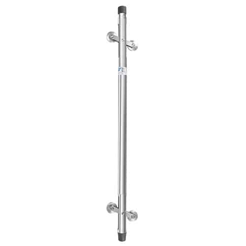
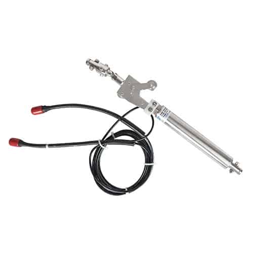
(b) In-Place Inclinometer:
 In-Place Inclinometer
Figure 2: In-place inclinometer general placement
An In-place Inclinometer consists of the following components:
- Bottom wheel assembly
- In place Inclinometer sensor
- Spacer tubing (length: need to specify as per the requirement)
- Placement tubing (Topmost part)
- Suspension kit
- Protective cover
- Junction box
- Data Logger: ESDL-30
In-place inclinometers are further divided into two types – Uniaxial and Bi-axial. The biaxial in-place tilt indicators consist of a couple of MEMS sensors attached at 90°.
How does an inclinometer work?
The inclinometer probes are built using two types of accelerometers:
Servo-Accelerometer: The force-balanced sensing elements housed in an inclinometer probe detect the change in tilt (from reference). The probe consists of a couple of biaxial servo-accelerometers. It is fitted with two sets of spring-pressured wheels to guide the probe along the longitudinal grooves of the inclinometer casing.
MEMS Accelerometer: Such inclinometers are termed MEMS Inclinometers. Currently, the MEMS (Micro-Electro-Mechanical Systems) technology is being used to build the tilt sensor probe. The MEMS consists of mechanical elements, sensors, actuators, and electronics on a common silicon substrate through microfabrication technology.
Acceleration causes deflection of the proof mass from its center position. There are 32 sets of radial fingers around the four sides of the square-proof mass. These fingers are placed between plates that are fixed to the substrate.
Each finger and pair of fixed plates make up a differential capacitor. The deflection of the proof mass is determined by measuring the differential capacitance.
By this method, both dynamic acceleration (i.e. shock or vibration) and static acceleration (i.e. inclination or rotation) can be sensed. Signal conditioning is carried out within inclinometers so that a simple output signal is obtained.
This output can be used in conjunction with a calibration sheet to easily calculate the amount of tilt that has occurred.
What is the inclinometer installation procedure?
Inclinometers can be installed in two ways:
1. Vertical Inclinometer Installation
The vertical inclinometer system is used for measuring relative horizontal displacements affecting the shape of a guide casing, embedded in the ground or structure.
A near-vertical gauge well is constructed by installing the inclinometer casing in a borehole and embedding it in an earth/rockfill or concrete structure during and post-construction.
The inclinometer probe is then passed through the entire length of the gauge well from bottom to top, taking readings at fixed predetermined intervals.
A probe (torpedo) consisting of a couple of precision accelerometers senses the inclination of the access tube 90° to each other. The bottom end of the guide casing serves as a stable reference (datum) and must be embedded beyond the displacement zone.
Relative displacement over time is determined by repeating measurements at the same depths and comparing data sets.
2. Horizontal Inclinometer Installation
The horizontal inclinometer system is installed to monitor the profiles of settlement or heave under storage tanks, embankments, dams, and landfills.
The horizontal inclinometer probe consists of a force-balanced servo-accelerometer which measures inclination from horizontal in the plane of the probe wheels.
A change in tilt angle is noted, and this indicates that the movement has occurred. The movement is calculated by finding the difference between the current inclination reading and the initial reading while converting the result to a vertical distance.
What is an inclinometer used for?
1. Monitoring retaining structure’s performance: The performance of retaining structures, such as sheet pile walls, soldier pile walls, or mechanically stabilized earth (MSE) systems is adversely affected by lateral pressures or ground movements.
Deformations in retaining structures could occur during and after construction. The inclinometer system is designed to measure the magnitude of tilt and differential deformation behind or within the wall face.
The inclinometer casing can be installed vertically in boreholes, adjacent to the wall face, or can be embedded within structural elements. Traversing-type inclinometer probes are usually used to determine the relative shape of the retaining structure and changes in it over a while.
2. Landslide Monitoring:
 Landslide Monitoring
Figure 3: In-place inclinometers installed at Cabo Fort, Goa
The determination of the depth and thickness of slide shear zones, and the magnitude, rate, and direction of landslide movement are critical aspects of landslide monitoring. Inclinometer casings are installed inside the boreholes, at multiple locations, depending upon the landslide size.
Inclinometer sensors are perfect for measuring the small levels of ground creep or shear zone movement.
The traversing type inclinometers measure the depth of landslide shear displacement. They can also be used to measure the rate of movement.
3. Monitoring Slope Stability: Slopes in cuts or fills embankments can be monitored for stability during and after construction. In such cases, the inclinometer casings are installed inside the boreholes, similar to landslide monitoring.
4. Monitoring Excavations: The impact of excavations is monitored to study its effect on nearby structures, utilities, and other critical facilities. In such cases, inclinometer casings are placed inside the vertical boreholes located between the excavation boundary and the nearby facilities.
The inclinometer casing can also be installed in the excavation system.
5. Monitoring during Tunnel Drilling: Inclinometers can be used to monitor stress-relief ground movements and possible displacement of rock blocks during the construction of tunnels and shafts. Gradient meters are used to verify the adequacy of ground supports, detect potential flaws in the construction approach, and serve as a warning system for potential ground failure.
6. Monitoring Pile and Drilled Pier Performance: Inclinometers can be used to measure the deformation of deep foundations subjected to large lateral loads. The level meter/tilt sensor casing can be embedded within or attached to structural elements.
Encardio Rite’s Models of Inclinometers
Encardio Rite deals with one of the most advanced MEMS digital inclinometer systems and in-place inclinometers. The Encardio Rite’s Models of tilt indicator/tilt sensor/slope alert/slope gauge/gradient meter/gradiometer/level gauge/level meter include:
- Model EAN-26M Horizontal Inclinometer
- Model EAN-26M-2 Vertical Inclinometer System
- Model EAN-52MV In-Place Inclinometer with GPRS/GSM Transmission
- Model EAN-53MW IPI with RF Transmission
- Model EAN 61MS 3D Inclinometer with Settlement
- Inclinometer Casing – Attached & Separate Couplings
1. Digital Inclinometer System Model EAN-26M:
 Digital Inclinometer System Model EAN-26M
Encardio Rite’s Model EAN-26M is one of the most advanced MEMS high-precision digital inclinometer systems. It uses the capability of high computational power and large high-resolution color display of today’s Android mobile phones. Hence, it can also be called an Android Inclinometer.
The mobile phone uses a wireless Bluetooth connection to communicate with the inclinometer reel unit. Gone are the days of frayed cable and unreliable slip ring connection between the reel and the handheld readout units. The EAN-26M digital inclinometer system is much lighter in weight and is very much liked by field personnel who have to carry the system from borehole to borehole for logging.
The digital inclinometer system consists of a traversing-type digital tilt-sensing probe that is connected to a reel unit kept at the borehole top. The reel unit consists of a winding reel that holds the cable and a wireless Bluetooth relay unit that sends the digital probe data to the mobile phone. A rechargeable battery in the reel unit supplies power to the whole system.
Specifications of Digital Inclinometer System:
| System Accuracy | ± 2 mm/30 m (± 0.1 in/100 ft) |
| Cable | 6 mm Ø, 2 core kevlar reinforced polyurethane sheathed |
| Cable reel up to 100m (330 ft) | 300 mm Ø (flange) |
| 100-200m (330-650 ft) | 380 mm Ø (flange) |
2. Digital Inclinometer System – Vertical- Model EAN-26M-2:
Encardio Rite Model EAN 26M-2 is a Vertical Digital Inclinometer System that makes use of a biaxial tilt-sensing probe and a reel unit. The reel unit is designed with a winding reel that secures the cable and a wireless Bluetooth relay unit that transfers the probe data to the data logger.
The sensor is also equipped with a rechargeable battery in the reel unit that powers up the whole system. The operating cable graduated at 0.5m (2ft) intervals includes a high tensile straining member. The cable is also provided with easy access through a reel. The probe can be used with all standard inclinometer casings – OD 70 mm (2.75″) & 85 mm (3.34″).
To stay in touch with the inclinometer reel unit, you can use a mobile phone readout using a wireless Bluetooth connection.
Specifications of Vertical Inclinometer System:
| Measuring Range | ± 30° of vertical |
| Resolution | ± 0.008 mm/500 mm (± 0.0004 in/24 in) |
| Temperature Limit | – 20° to 70°C |
| Dist. Between Wheels | 500 mm (2 ft) |
| Dimensions | 25.5 mm Ø x 685 mm long (excluding wheel arm) |
| Probe Weight | 1.4 kg |
3. In-Place Inclinometer System with GPRS/GSM – Model EAN-52MV:
Encardio Rite’s Model EAN-52MV vertical in-place inclinometer is used to measure the lateral movement of earthworks or structures.
It provides significant quantitative data on the magnitude of inclination or tilt of a foundation, embankment, or slope and its variations with time. It also provides the pattern of deformation, zones of potential danger, and effectiveness of construction control measures undertaken.
Its data logging and real-time monitoring feature help to provide early warning in case of failures. It also helps in observing the behavior of ground movement after construction and indicates potentially dangerous conditions that may adversely affect the stability of the structure, its foundation, and its appurtenant.
A suspension stainless steel wire rope is available to position a single or group of sensors where the profile of the entire borehole is not of interest, but only a specific portion needs monitoring.
Specifications of In-place Inclinometer System:
| Sensor | Uniaxial or biaxial sensor |
| Measuring Range | ± 15° |
| Accuracy | ± 0.1% fs |
| Resolution | ± 0.05 mm/m (8 arc seconds) |
| Output | SDI-12 serial output |
| Temperature Range | -20°C to 80°C |
Wireless In-Place Inclinometer System Model EAN-53MW
The Encardio Rite Model EAN-53MW is one of the most advanced wireless in-place inclinometer (IPI) systems, designed to measure the lateral movement of earthworks or structures. The wireless IPI system is used in critical applications where real-time monitoring and early warning are required to protect life and valuable assets.
The wireless IPI system primarily consists of an array of inclination sensors with SDI-12 digital interface, placed inside an inclinometer gauge well-connected to a wireless mesh network with Node and Gateway, to enable real-time monitoring.
The data logging and real-time monitoring feature of the wireless inclinometer helps to provide early warning in case of failures. The innovative wireless mesh network used in the system has the advantage of reliable data transfer over long distances, without any delay.
Specifications of Horizontal IPI:
| Sensor | Uniaxial or biaxial sensor |
| Measuring Range | ± 15° |
| Accuracy | ± 0.1% fs |
| Resolution | ± 0.05 mm/m (8 arc seconds) |
| Output | SDI-12 serial output |
| Temperature Range | -20°C to 80°C |
3D Inclinometer with Settlement – Model EAN-61MS
Encardio Rite Model EAN-61MS is an in-place 3D Inclinometer with Settlement (IPIS) system that finds its application wherever lateral movement along with settlement/heave has to be monitored in a structure/borewell. It is also extensively used in the measurement of lateral movement and settlement in soil, slopes, earthworks, and structures like an embankment, dams, diaphragm walls, etc. It will also be used for landslide area monitoring.
The Inclinometer is curated for accurate data on the magnitude of lateral movement along with settlement or heave and its variations with time. It also presents the pattern of deformation, potential danger zones, and the effectiveness of the undertaken measures. The data logging and real-time monitoring feature provides timely warnings and alerts in case of any failures.
The main benefit of the IPIS system is that it allows online monitoring of transverse movement as well as settlement using the same borehole/gagewell. This was not possible with any other sensors until now.
Specifications of IPIS system:
| Probe | Biaxial MEMS sensor (monitor X-Y); contactless magnetic sensor (monitor Z); with SDI-12 digital interface |
| Measuring range | ± 15° (X-Y), 100 mm (Z) |
| Accuracy | ± 0.1% fs |
| Temperature range | -20°C to 80°C |
| Output | SDI-12 digital (serial) output |
| Speed | Speed: 1200 bits/sec |
| Supply operating range | 12 – 16 V; Separate battery pack (power supply) required of ~15 V |
Features of Encardio Rite’s Inclinometer Systems
- Encardio Rite’s inclinometer systems are reliable, accurate, and simple to read with rugged and robust construction.
- They have excellent temperature stability.
- The inclinometer sensors can be easily connected to a remote data acquisition system for continuous monitoring.
- The inclinometer sensors use easily available Android OS-based GSM/GPRS capable mobile phones as handheld readout units.
- The phone provides a high-resolution vivid color display of readings and graphs.
- Wireless Bluetooth connection eliminates cable between the rotating reel and mobile phone readout.
- Mobile phone memory capacity allows local storage of more than 1 million data points.
FAQs
1. What is an inclinometer?
An inclinometer is a sensor used to measure slope, tilt, or deformation of a structure relative to gravity. It provides critical data during activities like tunneling, excavation, and construction to monitor structural stability.
2. What are the types of inclinometers?
Encardio offers two main types:
- Manual/Digital Inclinometers: Includes a probe, cable reel, and Android-enabled readout.
- In-Place Inclinometers (IPI): Permanently installed for real-time monitoring of slopes, embankments, and structural movements.
3. How does an inclinometer work?
Inclinometers use accelerometers (Servo or MEMS) to detect changes in tilt or displacement. Data is collected using probes and processed via digital interfaces or mobile readouts to calculate inclination.
4. How are inclinometers installed?
- Vertical Installation: Monitors horizontal displacements in boreholes or structures.
- Horizontal Installation: Measures settlement or heave under embankments, tanks, or landfills.
5. What are inclinometers used for?
Inclinometers are essential for:
- Monitoring retaining walls and slopes.
- Landslide detection and prevention.
- Stability analysis during excavations and tunneling.
- Assessing pile and pier performance under lateral loads.
6. What models of inclinometers does Encardio offer?
- EAN-26M: High-precision digital inclinometer with Bluetooth connectivity.
- EAN-52MV: GPRS/GSM-enabled inclinometer for real-time monitoring.
- EAN-53MW: Wireless inclinometer with mesh network for remote data transmission.
- EAN-61MS: 3D inclinometer with settlement monitoring.
7. What are the features of Encardio inclinometers?
- Robust and accurate sensors with excellent temperature stability.
- Continuous monitoring capability with remote data acquisition.
- Android-enabled mobile readouts with wireless Bluetooth connectivity.
- Reliable construction designed for long-term field use.
8. What is the accuracy of Encardio inclinometer systems?
The accuracy varies by model but typically ranges from ±0.1% full scale for in-place systems to ±2 mm/30 m for digital inclinometers.
9. Why choose Encardio inclinometers?
Encardio Rite’s systems combine advanced MEMS technology, robust construction, and real-time monitoring features. They are trusted worldwide for reliable data in critical applications like slope stability, tunneling, and landslide monitoring.