Inclinometers are very important geotechnical instruments that assist in the accurate measurement of the magnitude of inclination or tilt, and its variation with time. They are usually employed for structures like retaining/diaphragm walls, piles, buildings, etc.
As the leading manufacturer and supplier of inclinometers, Encardio Rite offers a huge range of geotechnical instruments that have been applied in many prominent and well-known structures all over the world.
In this article, we are looking at the latest innovation for the Encardio team and a never-seen-before geotechnical instrument called the In-place 3D Inclinometer Settlement System.
Let’s find out what it is all about.
Introduction to In-place 3D Inclinometer System
Encardio Rite Model EAN-61MS in-place 3D Inclinometer System (IPIS) is designed for the measurement and monitoring of lateral movement along with settlement/heave in a borewell or on a structure.
This makes it extremely useful for the measurement of settlement in soil, earthworks, structures, or slopes including retaining/diaphragm walls, embankments, deep foundations, dams, etc. It is also designed to provide information about the zones of potential danger, the pattern of deformation, and the effectuality of the construction control measures.
The new innovative instrument also finds wide application in monitoring landslide areas.
Along with the measurement, it is also employed for monitoring as its data logging, and real-time monitoring features and capabilities allow early warnings of any potential threat or failure.
One of the applications of the geotechnical instrument is that it helps in the observation of the ground movement behavior after construction and registers any potentially dangerous conditions that may negatively impact the stability of the structure.
The most attractive feature of the Encardio Rite IPIS System is that it allows online transverse movement as well as settlement using the same borehole. This was not possible with the currently available instruments.
We will be looking at the inclinometer in detail, but let’s find out more about its application and features.
Read more: Inclinometer: Types, How It Works, & Uses
Application- Where is it used?
- The instrument is largely used to measure lateral movement and settlement/heave of embankment fills and landslide areas above dams, highways, earthworks, structures, etc.
- The In-place inclinometer finds application in the monitoring of deformation of embankments, retaining walls, etc.
- It is also applied in stability investigation, construction control, and monitoring of ground movement caused by tunnel construction or any other excavation.
Features – In-place 3D Inclinometer System
- Measures the complete 3D(X-Y-Z) profile of the borehole/gage well
- Is reliable, accurate, and very easy to read
- Designed with a rugged and robust construction
- Allows the probes to be removed, reconfigured, and reused with different boreholes or projects
- Provides Excellent temperature stability
- Allows Easy connection to our data loggers with extremely simple and user-friendly configuration software.
Read more: Vertical In-place Inclinometer – Operating Principle & Installation
How it works -An Overview
Here’s how the In-place 3D inclinometer Settlement system works.
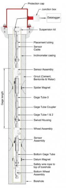
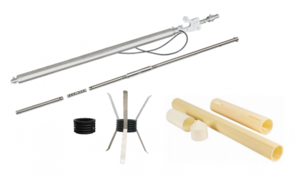
A series of ABS inclinometer access tubes attached with telescopic coupling are installed in a borehole or embedded in earth/rockfill or concrete structure during construction or fixed to the vertical face of a completed structure. The ABS casing is fitted with special magnet rings at intervals.
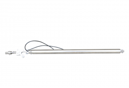
The IPIS system is equipped with a series of probes that are placed in the inclinometer casing in a continuous array to measure the movement zone. Each probe contains a high-accuracy biaxial MEMS sensor to monitor inclination or lateral movement (X-Y). It also provides a contactless magnetic sensor which is employed to monitor settlement or heave (Vertical movement – Z) placed in a waterproof stainless steel enclosure.
These sensors are used to measure the tilt and settlement in continuous segments, allowing for accurate monitoring of a change in the profile (x-y-z) of the inclinometer casing. Each probe is also equipped with pivoted sprung wheels that are connected through gage tubes which rest inside the grooves of the inclinometer casing.
The length of the spacer tubing is what decides the distance between each sensor; and the length of each segment where the tilt is monitored.
Our Inclinometer sensor possesses a displacement range of 100mm which helps to measure the expected settlement/heave. It is labelled at three locations which are the two ends and the middle for ease in setting.
A coarse adjustment of 5 mm / 50 mm / 75 mm and a fine adjustment of 50 mm (± 25 mm) is provided in the gage tube for the positioning of the settlement sensor over the ring magnets. Even the gauge tube is put together in parts.
There are several advantages of the digital probes over the conventional analog probes. For example, if we are using a string of analog probes, it becomes a very costly and complex process to route the individual sensor cable to the top. It also increases the weight of the assembly, thereby limiting the number of sensors that can be used in a single borehole.
For this reason, when we have to employ several sensors, SDI-12-equipped 3D probes are the perfect choice as they aren’t restrictive when it comes to accommodating a larger number of individual signal cables inside the borehole.
In Encardio Rite’s IPIS system, a 3 conductor bus cable requires to be threaded in a daisy chain fashion that connects each probe to the next immediate neighbour. This is then connected to the top of the borehole and then directly to the datalogger, without any multiplexer.
If we compare the cost of digital probes and the conventional analog probes, the digital one might be costlier but saves on the cost of multiplexers which balances the cost.
Read more: Wireless In-Place Inclinometer – Features and Working
How do you measure with the IPIS system?
During the initial process, the magnetic probe is employed to register the precise location of the magnets mounted on the casing. Once the location is known, it can be adjusted with the help of threads over expandable gage tubes. This also depends on whether heavy settlement is needed at the site.
When there is a subsurface movement in the ground, it leads to displacement in the inclinometer casing. The displacement further causes a change in the tilt of the in-place tilt sensors. The output reflects the change, proportional to the tile i.e., the angle of inclination from vertical.
If there is any settlement/heave taking place, it is estimated with the help of the change in the position between the contactless magnetic sensors and the magnet rings positioned outside the inclinometer casing. Therefore, the settlement/heave of all the sensors is measured concerning a reference, which can be a datum magnet that is installed at the bottom of the borewell casing or the top of the borewell.
To calculate the deformation of the casing, subtract the initial deviation from the current deviation. It is also possible to get the entire profile of the access tubing provided that one end of the access tubing is secured. You can then calculate by adding the reading of successive sensors and settlement at the desired levels.
The different profiles can be compared to get the lateral displacement (X-Y) of the gage well along with the settlement (Z) at different depths over some time. We advise always measuring the initial Northing (X) and Easting (Y) positions of the casing top and the elevation of the pipe top after the casing is set, for future correlation/cross-reference. It is also a good practice to take down the initial readings with a manual digital inclinometer system and a magnetic probe, in case you may ever need it in the future.
Read more: IPIS: The Game-Changing Solution for Efficient Monitoring
This brings us to the end of our blog on the In-place 3D inclinometer/settlement system. Hope this helped you understand the process and the working of the instruments better.