The digital inclinometer system is a reliable instrumentation system that displays the measured data through an Android mobile phone. Its readout has built-in data storage facilities and the capability of transferring stored data to a computer.
The inclinometer probe operates in a plastic grooved casing (inclinometer casing) which may be “built-up” with embankment fill, inserted into boreholes, or attached externally to structures or hillsides.
The installation procedure of inclinometers is a bit trickier and requires special assistance. Here is how the inclinometer casing installation is done to further install the digital inclinometer in a borehole, diaphragm wall, or dam settlement.
Digital Inclinometer – Operating Principle
Start by making a near-vertical gauge well by installing the inclinometer casing in a borehole, embedding it in an earth/rock fill or concrete structure during construction, or fixing to face of a completed structure.
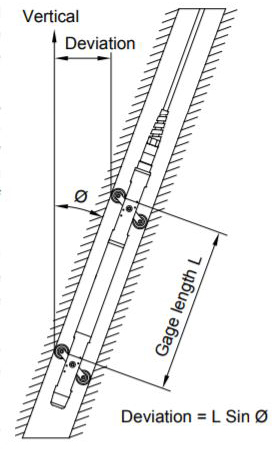
Pass the inclinometer probe through the entire length of the gauge well, taking readings at fixed pre-determined depths from bottom to top. A dual accelerometer probe measures the inclination of the casing in two planes at right angles to each other.
The voltage output from the probe is directly proportional to the sine of the angle of inclination of the long axis of the probe from the vertical. A positive output voltage indicates a negative angle of inclination.
A set of initial base readings, known as the reference datum is taken at given depths within the gauge well. The subsequent reading sets are correlated with this reference datum. All subsequent readings are taken over a while at identical depths, thereby indicating the rate, magnitude, and direction of lateral deformation.
The inclination is displayed in terms of angular or horizontal displacement on the electronic readout equipment at ground level with the operator.
Digital Inclinometer System
The Encardio Rite Model EAN-26 digital inclinometer system consists of:
- Access casing and fittings
- Tilt sensing probe
- Interconnecting cable with reel and cable holder
- Mobile phone data logger
Access Casing and Fittings
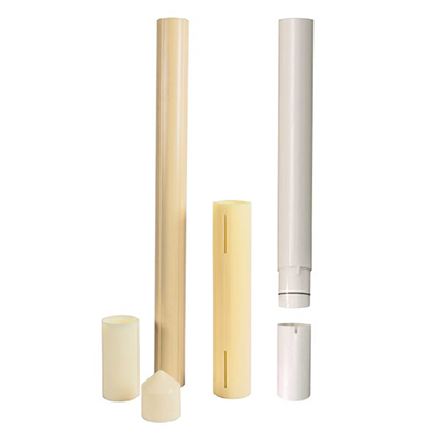
The access casings can be of different types and sizes. The ABS inclinometer casing is one of the most preferred ones. It has longitudinal keyways, specially produced to close tolerances. The wheels of the tilt-sensing probe can run smoothly inside these keyways.
It is a self-aligning ABS tubing, 70 mm o.d., 58 mm i.d. 3 m in length. Two kinds of couplings are available to rapidly join access casing. Fixed couplings are normal and telescopic couplings are available in case a settlement is expected to take place. The design of these couplings ensures that the correct alignment of keyways is maintained throughout the depth of the gauge well.
| Also Read: Digital Inclinometer System: Introduction & How Does It Work |
Digital Inclinometer Probe
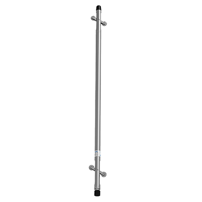
The digital inclinometer or the tilt sensing probe measures angles of inclination from the vertical in two planes oriented at 90° (orthogonal) to each other. The inclinometer probe has a stainless steel construction and is fitted with two pairs of pivoted sprung wheels that can rotate freely.
The standard gage length between the wheels is 500 mm (or 2 feet). The spring-loaded wheels help to accurately position the probe centrally inside the gage well at any required depth. The precision-grooved casing forms an integral part of the gage well.
The cylindrical portion of the probe has a diameter of 25.4 mm and a length of 685 mm. The probe consists of two integral precision accelerometers, one with its axis in the plane of the wheels and the other at 90 degrees. The probe senses horizontal deviation between the probe axis and the vertical plane, simultaneously in the ‘X’ and ‘Y’ directions.
Interconnecting cable with reel and cable holder
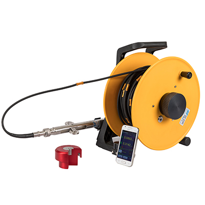
Figure 1: Cable reel with read-out
A cable reel is available for the specified length of cable. A PU-sheathed two-core cable is clamped at every 0.5m (or 2 feet) with copper ferrules. The ferrules are number engraved at every meter. A four-pin connector is provided for connecting the read-out to the probe.
Android Mobile Phone Data Logger
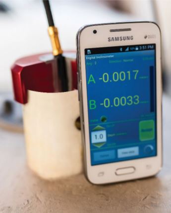
Figure 2: Readout Unit
The digital inclinometer system uses a mobile phone as a data logger. Any mobile phone with minimum required features can be used for this application.
The inclinometer app running on the phone can take borehole readings and store them in memory. The app can show borehole logs in tabular format and create plots of borehole data instantly after the borehole reading is complete.
Borehole data files are created automatically while saving the borehole log. These files can be recreated from the app database when needed or can be uploaded to a remote server through GPRS/3G/Wi-Fi.
Digital Inclinometer Installation Tools & Accessories
It should be ensured that the following tools and accessories required for proper installation of the inclinometer PVC casing and for taking readings are available:
- Toolbox
- 50 mm wide waterproof sealing tape
- Spanner 16/18
- Screwdriver 100 mm
- Voltage tester
- Pliers 150 mm
- Flat file 150 mm
- Safety line or tension cable in case the hole is very deep
- Clean water supply to clean casing
- Hand saw with three 30 cm blades
- Casing collar protection if required
- Grout tube – requisite length
- Acetone
- Aluminium pop rivets – four per joint plus some extra
- Pop rivet gun
- Drill with a 3.15 mm spare drill bit.
- Casing clamps – 2 sets
- Plumb bob with 5 m chord
- Casing cap with guy ropes (for embankment installations)
- Casing ‘U’ clamps and grout bolts (For installation on concrete structures)
Inclinometer Casing Installation Procedure
The ABS casing may be installed in a borehole, embedded in an earth/rock fill or concrete structure during construction, or fixed to the vertical face of a completed structure.
Preparing the Inclinometer Casing
- Clean the inside of the bottom cap and outside of the lower end of a casing with a moist cloth (use isopropyl alcohol if greasy).
- Push the bottom end cap over the casing. Fix it to the casing with four pop rivets using a 3.2 mm diameter drill bit. Riveting should be done at diametrically opposite points 90° apart.
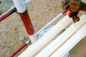
Figure 3
- Seal joint between the bottom cap and casing with mastic waterproof tape. One round of this tape with a 10 mm overlap is sufficient.
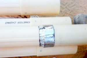
Figure 4
- Press the tape firmly after applying, to remove any air pocket.
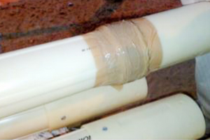
Figure 5
- Additionally, wrap 3-4 rounds of BOPP tape with a little force over mastic tape for extra protection. Proper sealing is necessary to prevent intrusion of backfill materials inside the casing.
NOTE: Pre-assembly and storage of inclinometer casings should be done in the shade as prolonged exposure to direct sunlight might distort the tubes.
Fixed Coupling
Attach a fixed coupling to one end of all other casings to be installed. Clean mating surfaces with a moist cloth (use isopropyl alcohol if greasy).
Push 160 mm long fixed coupling over the end of the casing up to a maximum allowable depth of around 80 mm. Drill holes with 3.2 mm bit and pop rivet coupling to the casing at four places (the position for two pop rivet holes is marked on the coupling; the other two holes should be symmetrically drilled).
Seal the joint between the fixed coupling and casing with mastic waterproof tape and BOPP tape as described above.
Telescopic Coupling
- Telescopic couplings are mostly installed in embankments where settlement takes place during construction. They are sometimes installed in boreholes where settlement or heave may take place.
- The telescopic coupling has two sets of diametrically opposite longitudinal grooves which facilitate a total movement up to 150 mm (refer to figures 6 and 9). Coupling is secured to adjacent casings with a set of four screws and nylon washers.
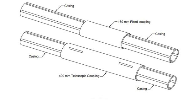
Figure 6: Fixed and Telescopic coupling
- Attach a telescopic coupling each to the end of all other casings to be installed except the one with the bottom cap. Clean mating surfaces with a moist cloth (use isopropyl alcohol if greasy).
- For applications in which only settlement takes place, push 400 mm long telescopic coupling over the end of the casing up to the maximum allowable depth of around 195 mm. Drill two holes with 2.5 mm bit at the end of the slot of coupling as shown in figures 7 and 8. Fix coupling to the casing with self-tapping screws and washers at position A. (Position B is the location where the other casing will be drilled during installation at the site).
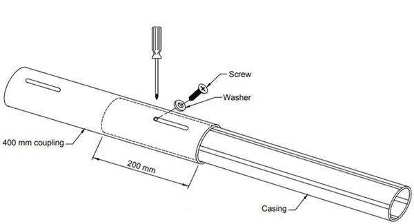
Figure 7: Do not over tighten screw
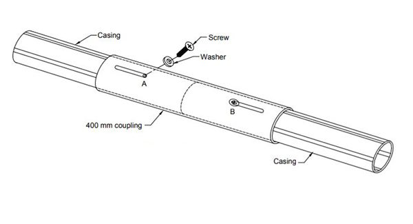
Figure 8: For settlement monitoring 2.5 mm holes will be required to be drilled at A and B
- Pull the casing out so that screw comes to position C as shown in Figure 9. Tighten screws. When the other casing is finally assembled at the site, a space of 150 mm will be left between the casing ends to take care of settlement.
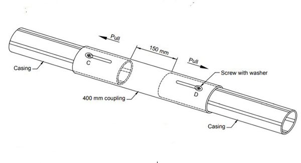
Figure 9: Installation positions of casing ends & telescopic coupling for settlement monitoring
- In case settlement/heave both are possible at the location where the casing is to be installed, adjust the position of screws in the groove for an appropriate length of travel as shown in Figure 9.
- If such a casing is required to be lowered from the top into a borehole, aluminium pop rivets may have to be used to keep the coupling in position (refer to Figure 10).
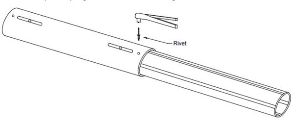
Figure 10: Telescopic casing preassembly for heave/settlement applications
- Seal the joint between the telescopic coupling and casing with mastic waterproof tape and BOPP tape as described above. The casing assemblies are now ready for installation. Carefully transport them to the site when required.
| Also Read – Inclinometer: Types, How It Works, & Uses |
That was all about the installation procedure of an inclinometer casing. Once the ABS casing is fully prepared, you can proceed with the digital inclinometer installation.