Geotechnical instrumentation and monitoring is a vast field that includes several monitoring instruments such as piezometers, tiltmeters, strain gauges, beam sensors, extensometers, etc.
Since extensometers are one of the most significant monitoring instruments, let us give you a better insight into its working principle, construction, specifications, and application areas.
What Is An Extensometer?
An extensometer is a high-precision instrument specially designed for geologists or civil engineers to measure the elongation of a material under stress. This instrument is perfect for tensile tests.
It can also determine yield strength, tensile strength, yield point elongation, strain-hardening exponent, and strain ratio.
Besides this, extension meters have a huge scope of work in the geotechnical field. They are available in various types and sizes depending on the application area.
How does an extensometer work?
Usually, the extensometers are classified as contact, non-contact, laser, and video extensometers.
However, the working principle of extension meters depends on their type as well as the application area. Encardio Rite deals with a wide range of extensometers, including magnetic, electrical, mechanical, and soil extensometers. All of these extension meters have different working principles.
Magnetic Extensometer
The magnetic extensometer system is designed to measure settlement or heave of the soft ground under the influence of loading or unloading due to the construction of embankments, fills, buildings, and structures.
Lateral movement at any level within a soil mass may be assessed by monitoring the location of magnetic targets positioned over a near-horizontal access tube. The lateral ground movement may be in abutments, foundations, or embankments, and a consolidation-induced settlement in embankments and foundations.
Electrical Extensometer
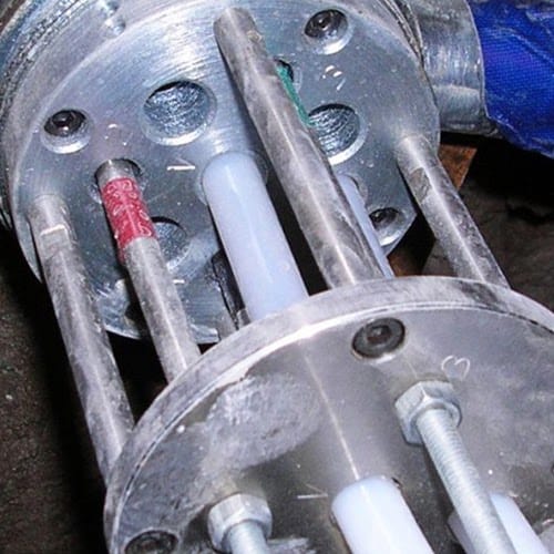
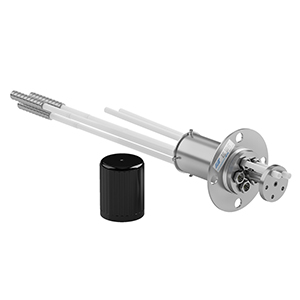
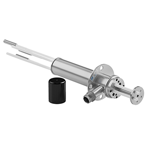
The electrical borehole extensometer incorporates a vibrating wire transducer for the measurement of displacement. A groutable reinforced bar anchor (1) is attached to fiberglass (2. a) or AISI 410 stainless steel (2. b) connecting rods of appropriate length, as specified in the design.
Fibreglass connecting rods are supplied from the factory in single lengths. The connecting rods are enclosed inside heavy-duty protective tubing to allow for free movement. The displacement sensor is coupled to the connecting rod using a link plate and lock nut.

Mechanical Extensometer
The borehole extensometer measures the extension (displacement) that takes place with time in a borehole or several boring holes in a rock mass. It essentially consists of one or more anchors and a reference plate. The anchor or anchors are set in the same borehole or different boreholes drilled adjacent to the first borehole.
They help to accurately measure the distance between the various anchors concerning the reference plate and monitor their relative displacement with time. It is usually assumed that the deepest anchor is in the stable ground and so any change in the anchor spacing gives information about the settlement of the foundation taking place.
Soil Extensometer
The soil extensometer uses a vibrating wire sensor for monitoring displacement. The system consists of a sensor assembly with flanges that are mounted with adaptors, adjustment units, sockets, and extension rods between two anchors to monitor the horizontal movement of surrounding soil.
The system is enclosed in telescopic PVC tubing with proper ‘O’ ring seals to eliminate friction between the rods and surrounding soil and to prevent any ingress of water.
The extensometer system is supplied with different gauge lengths (gauge length is the distance between two anchors).
Several extensometer units can be connected in series to measure incremental displacements over large distances. The movement of relative position between two anchor channels at the ends of the soil extensometer is representative of the mass movement.
The relative movement between the anchors causes a change in the output of the vibrating wire sensor. This output can be measured by the Encardio Rite model EDI-51V portable read-out unit/datalogger or monitored by a remote model EDAS-10 data acquisition system.
The initial reading is taken as the datum. The difference between subsequent readings and initial readings gives the magnitude of the movement.
Uses of extensometer in the geotechnical field
- To determine how the roof or wall of the mine, underground cavity, or tunnel behaves during excavation operation & to study the effectiveness of the support system.
- To predict potential roof or wall fall before it occurs. Roof or wall fall in an underground cavity is almost invariably preceded by measurable sag as the strata open up, and the movement usually occurs at an increasing rate as fall conditions approach. Unsuspected roof and wall fall conditions are approached which may result in serious accidents.
- To measure and monitor the movement in a slope or foundation due to the excavation of underground cavities or due to the construction of a heavy structure like concrete, rock fill, masonry, or earth dam over the foundation.
- To measure the e-someter work? types and sizes depending on the application area.
- To measure horizontal and vertical movement in foundations and embankments.
- To measure the movement of natural and cut slopes, quarry, and mining excavations.
- To calculate the displacement of retaining walls, piers & abutments.
- To measure the displacement around tunnels & underground cavities.
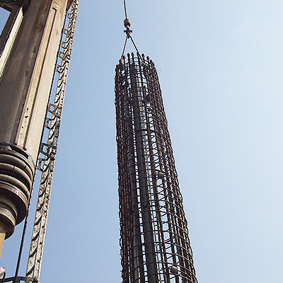
- They are used for highly accurate measurements of relative deformations of multiple segments along the entire pile length. To be specific, extensometers are used for the measurement of the variation of the distance between the pile head and a specific level of the testing pile.
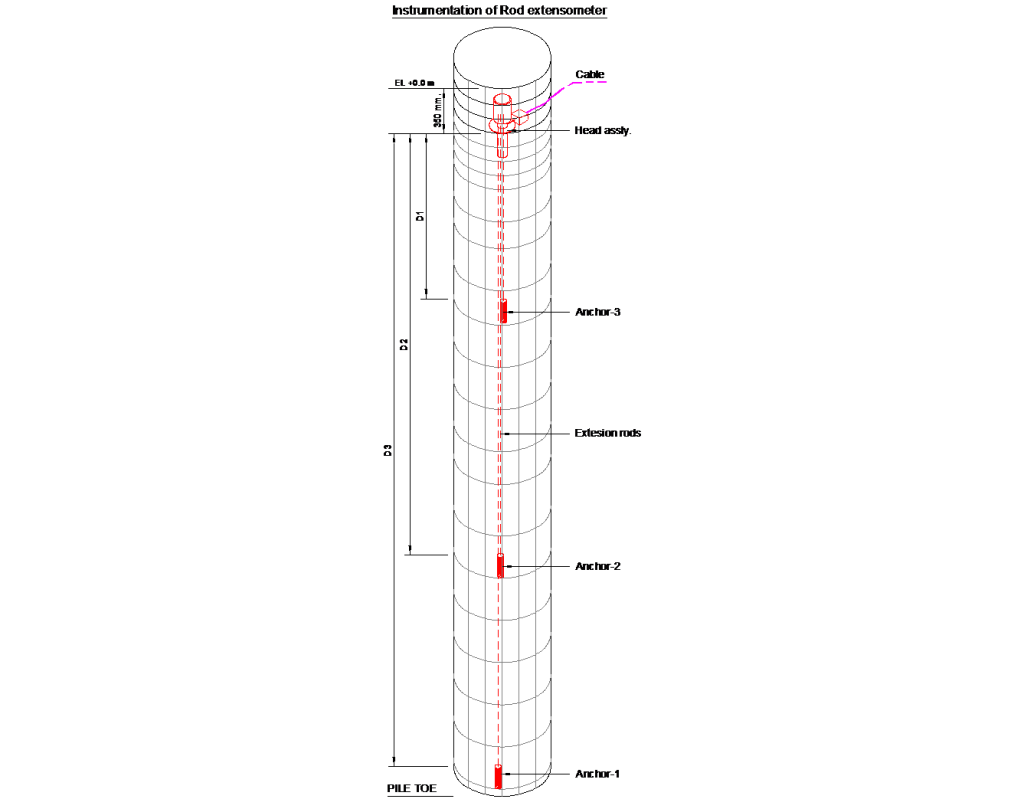
Figure 1: Typical installation of MPBX
What are the types of Extensometers?
Encardio Rite deals with some of the most reliable, high-precision, and robust extensometers in the industry.
- Model EDS-63U-D Mechanical Borehole Extensometer System
- Model EDS-64U-D Mechanical Orehole Extensometer System
- Model EDS-70V/EDS-70P Electrical Borehole Extensometer System
- Model EDS-71V/EDS-71P Electrical Borehole Extensometer System
- Model EDS-91 Magnetic Extensometer System
- Model EDS-92 Soil Extensometer
- Model EMA-11 Measuring Anchor
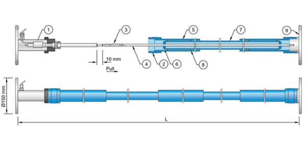
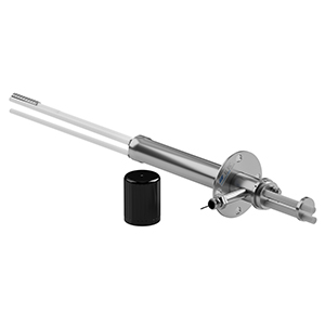
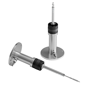
Model EDS-63U-D Mechanical Borehole Extensometer System

The Encardio Rite Model EDS-63U-D mechanical borehole extensometer is ideally suited for upward, downward, or inclined boreholes. It is a precision instrument designed to measure the deformation of rock mass and adjacent or surrounding soil.
Together with an anchor bolt load cell and tape extensometer, it is essential equipment for the investigation and monitoring of foundations, slopes & embankments and for studying the behavior of rock around underground cavities, tunnels, and mines.
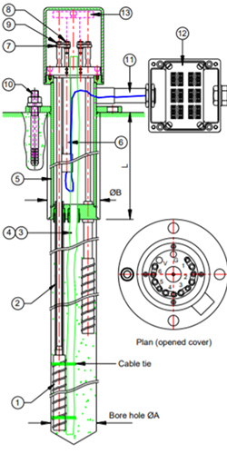
Diagram of Model EDS-63U-D Mechanical Borehole Extensometer System
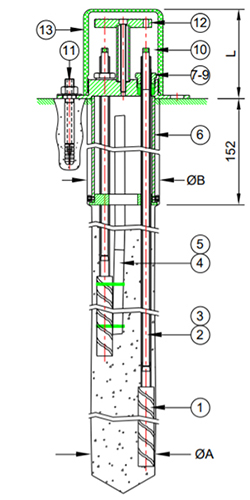
The groutable reinforced bar anchor (1) is attached to SS 410 stainless steel (φ 8 mm) or fiberglass (φ 6 mm) connecting rods (2) of appropriate length, as specified in the design.
The anchors are inserted into the borehole along with their respective connecting rods and fixed in position by cement grout. The connecting rods are protected from the cement grout by enclosing them in a heavy-duty protective tube (3), thus allowing for free movement and displacement.
The extension head consists of a reference head/flanged housing (6) and a protective cover (13). The flanged housing is grouted concentric with the borehole. The reference head has four grouting anchors (11) for fastening the extensometer head to the surface of the borehole.
The protective tube (3), grout tube (5), and vent tube (4) are secured to the reference head/flanged housing with rubber washers (8) and hollow bolts (9) to make the system leakproof. A reference plate (12) is used to measure the displacement of the anchor from the reference button (10) fixed on the connecting rod (2). Encardio Rite uses the convention that the depth of the anchor is calculated as the distance from the mouth of the borehole to the near end of the anchor.
Borehole Extensometer Installation Procedure
The measurement with Model EDS-63U-D borehole extensometer is economical, very reliable, and is preferred at locations where access to the mouth of the borehole is easily available.
Displacement readings are taken by measuring the depth of the near end of the connecting rod from a reference plate provided at the mouth of the borehole. A digital caliper/micrometer depth gauge with a resolution of 0.01 mm is used to take the readings.
EDS-63U-D Single/Multi-Position Extensometer
The Model EDS-63U-D borehole extensometer with up to three positions can be installed in a 3” φ NX (76 mm φ) borehole; with up to six positions, it can be installed in a 100 mm φ borehole.
Groutable Anchor
It is not possible to install expandable anchors effectively at locations where the rock formation is soft. Groutable anchor is ideally suited for such applications. In a borehole, it is usual to use a 20 mm φ, 500 mm long groutable anchor.
Don’t forget to check out this video on Model EDS-63U-D mechanical borehole extensometer:
Specifications of Model EDS-63U-D Mechanical Borehole Extensometer
| Type | Mechanical |
| Number of Points | 2-3 points; 76 mm borehole (EDS-63U/D)
4-6 points; 102 mm borehole (EDS-63U/D)
Single point; 50 mm borehole (EDS-64U/D) |
| Extension Rod | Stainless Steel or Fibre Glass |
| Anchor | Groutable or Packer |
Model EDS-64U-D Mechanical Borehole Extensometer System
The Encardio Rite Model EDS-64U-D single-position mechanical borehole extensometer is suitable for 50 mm upward, downward, or inclined boreholes. It is a precision mechanical instrument designed to measure the deformation of rock mass and adjacent or surrounding soil.
The construction, working principle, and specifications of Model EDS-64U-D Mechanical Borehole Extensometer System remain like that of Model EDS-63U-D Mechanical Borehole Extensometer System except that it is suitable for 50 mm upward, downward, or inclined boreholes.
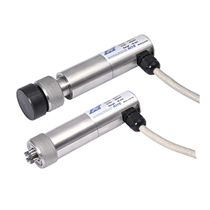
Model EDS-70V/EDS-70P Electrical Borehole Extensometer System
The Encardio Rite Model EDS-70V multi-point borehole extensometer is a precision instrument designed to help civil engineers and geologists in the measurement of deformation of rock mass & adjacent or surrounding soil.
Together with an anchor bolt load cell and tape extensometer, it is essential equipment for the investigation & monitoring of foundations, slopes & embankments and for studying the behavior of rock around underground cavities, tunnels, and mines. The borehole extensometer is an important instrument, especially in the investigation of underground cavities & landslides.
EDS-70V Electronic Extensometer
The Model EDS-70V borehole extensometer incorporates a vibrating wire transducer for measurement of displacement. A groutable reinforced bar anchor (1) is attached to fiberglass (2. a) or AISI 410 stainless steel (2. b) connecting rods of appropriate length, as specified in the design.
Fibreglass connecting rods are supplied from the factory in single lengths. The connecting rods are enclosed inside heavy-duty protective tubing to allow for free movement. The displacement sensor is coupled to the connecting rod using a link plate and lock nut.
Diagram Of EDS-70V Electronic Extensometer
EDS-70V can be ordered from the factory for monitoring settlement at up to six depths. It is suitable for a 3” Ф (~76 mm) borehole for up to 1~3 points & 4” Ф (~102 mm) borehole for 4~6 points.
The diameter at the mouth of the borehole is increased to 90 mm and 125 mm to house the head assembly. Spacer adjustment is provided optionally for movement more than the range in case of heave/settlement.
Model EDI-51V portable readout logger is used to measure the displacement of Model EDE-VXX vibrating wire linear displacement transducers. The readings can also be monitored remotely using the Model EDAS-10 data acquisition system.
Model EDS-70M Mechanical Extensometer
Model EDS-70M version of this borehole extensometer is available for taking the reading with a mechanical dial gauge. This model is supplied without the vibrating wire sensors.
At a later stage, this extensometer can be converted to take readings electronically by installing vibrating wire displacement sensors.
EDE-VXX Linear Displacement Sensor
Model EDE-VXX vibrating wire linear displacement transducer incorporates a vibrating wire sensor having a stroke of 50 mm (EDE-V05), 100 mm (EDE-V10) or 150 mm (EDE-V15). It converts the mechanical displacement to an electrical output in frequency form. This frequency output can be read or logged by the Encardio Rite model EDI-51V remote digital readout unit or Encardio Rite model EDAS-10.
Specifications Of Model EDS-70V/EDS-70P Electrical Borehole Extensometer
| Type | Vibrating wire/potentiometric |
| No. of points | 2 to 6 |
| Extension Rod | Stainless steel or fiberglass |
| Anchor | Groutable or packer |
| Sensor range | 50, 100, 150 mm |
Model EDS-71V/EDS-71P Electrical Borehole Extensometer System
The Encardio Rite Model EDS-71V electrical borehole extensometer is a precision instrument designed to help civil engineers and geologists in the measurement of the deformation of rock mass and adjacent or surrounding soil.
The construction, operating principle, applications, and specifications of the Model EDS-71V borehole extensometer are similar to those of the Model EDS-70V/EDS-70P Electrical Borehole Extensometer.
Model EDS-91 Magnetic Extensometer System
The Encardio Rite Model EDS-91V/H magnetic extensometer is used to measure vertical settlement or lateral movement depending on the application. Settlement or heave at various levels within a soil mass may be assessed by monitoring the location of magnetic targets that have been positioned over a near-vertical access tube.
Diagram of Model EDS-91 Magnetic Extensometer System
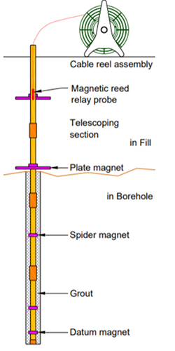
Two types of access tubing with telescopic coupling are available for the installation. For monitoring settlement only, regular access tubing is used. For monitoring lateral displacement along with the settlement, an inclinometer casing with telescopic coupling is used.
For vertical installation in earth fill, 3 m long tubes are connected, one by one, with telescopic couplings to keep pace with the fill operation. The magnets are located centrally on the lower-diameter tube.
For horizontal installations, similar telescopic access tubes are laid at the base of the trench, with magnet plates embedded in the trench floor. For monitoring a dead-end hole, a pull cable with an optional reel, cable return pipe, and a dead-end pulley assembly are available. Alternatively, for small-length holes, a push rod may be used.
Guide Tubing & Coupling
EDS-91/1.1:PVC access tubing, 26 mm i.d., and 32.8 mm o.d., 3 m long.
EDS-91/1.2:Extension/compression PVC access tubing for above, around 35.5 mm i.d. and 41.5 mm o.d., 1 m long.
EDS-91/1.3: ABS grooved tubing, 58 mm i.d., 70 mm o.d., length 3 m. Weight around 3 kg.
EDS-91/1.4:ABS grooved telescopic coupling (allows 150 mm compression). Weight around 0.5 kg
EDS-91/1.5: Return pipe same as EDS-91/1.1
Signal Receiver & Probe EDS-91/2.1
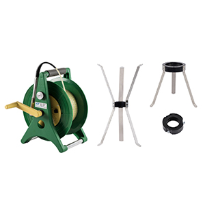
The probe, 22 mm Φ x 150 mm long has a reed switch encapsulated inside it in silicon rubber for protection against shock, corrosion, and ingress of water. It is connected to the signal receiver consisting of a reel with a battery pack, an on-off switch, a buzzer, and an LED by a flat measuring tape.
The measuring tape is virtually non-expandable, insulated flat, and 10 mm wide x 2 mm thick. The probe is available in tape lengths of:
Length ‘L’ (m):30, 50, 100, 150, 200, 300
Resolution:1 mm
Length ‘L’ (ft):50, 100, 150, 300, 500
Resolution:0.01”
The moisture-resistant electronics and standard 9 V PP-3 size battery are housed in a hub on the cable reel. The hub can be easily removed to replace the battery or check the electronics without disassembling the entire cable reel.
EDS-91/2.2: For centrally locating the probe in larger diameter access tubing, a 100 mm long adapter of diameter 6 mm less than that of the access tubing is available.
EDS-91/2.3:This is an alternative to EDS-91/4.2. It is an inclinometer-type adapter with two fixed wheels and spring-loaded wheels with a longitudinal distance of 30 cm.
Magnet targets
EDS-91/3.1: Plate magnet of 300 mm square size with center hole to slide over the access tubing.
EDS-91/3.2:Ring magnet is 57 mm Φ x 20 mm width for EDS-91/1.1 and 92 mm Φ x 20 mm for EDS-91/1.3 for the datum. Or (Ring magnet to be fixed permanently on the tubing for datum)
EDS-91/3.3: Spider magnet with 6 leaves for springing out in the correct position.
EDS-91/3.4:Spider magnet with 3 leaves for pushing down over access tube.
Dead End Pulley Assembly EDS-91/4.1
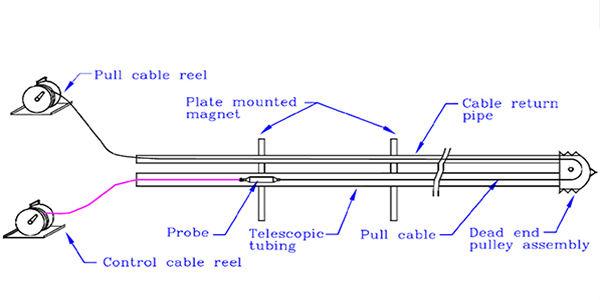
A dead-end pulley assembly is provided for horizontal installation for monitoring a dead-end hole.
Pull Cable Real EDS-91/5.1
In case of installations required for monitoring horizontal movement, a pull cable reel with cable return pipe is provided. It assists in moving the probe backward or forward through access tubing.
Specifications of Model EDS-91 Magnetic Extensometer System
| Range | 30, 50, 100, 150, 200, 300 |
| Resolution | 1 mm |
| Probe Dimension | 22 mm Φ, 150 mm long |
| Access Tube | PVC, 25.5 mm i.d., 32.5 mm o.d., 3 m long, fitted at both ends, with telescopic couplings having dimensions 35 mm i.d., 41.5 mm o.d., length 1 m, 2 m, 3 m |
| Range (ft) | 50, 100, 150, 300, 500 |
| Resolution | 0.1″ standard |
Model EDS-92 Soil Extensometer
The Encardio Rite model EDS-92 extensometer is used for monitoring displacement between two surfaces that may shift concerning each other with time. The soil extensometer finds major application in the measurement of lateral strains and settlement in or beneath earth/rock-fill embankments.
It is used in the measurement of foundation movements and controlling of natural and cut slopes. The displacement of retaining walls, bridge piers, and abutments can also be monitored by the soil extensometer.
It also measures displacement across construction joints in concrete and across joints/faults in the rock. The extensometers are usually installed in approximately 500 mm wide x 600 mm deep trenches. The extensometers are usually installed in approximately 500 mm wide x 600 mm deep trenches.
Model EMA-11 Measuring Anchor
The Encardio Rite Model EMA-11 measuring anchor (rock bolt extensometer), is a combination of a rock bolt and an extensometer. EMA-11 Measuring anchor is used to determine the load exerted on rock bolts.
It is a precision instrument designed to help civil engineers and geologists evaluate anchor system forces and their distribution within the bolt and hence its safety and effectiveness.
How Does Model EMA-11 Measuring Anchor Work?
The principal function of measuring anchors is to determine the depth where force is exerted on the bolt due to the loosening effects of rock.
Model EMA-11 measuring anchor consists of a steel hollow anchor/rock bolt with a precise 4-point extensometer integrated into it. The measuring bars inside the hollow bolt have anchor points at each quarter of the total length so that the extension of the rock bolt and the corresponding forces can be determined.
Measurement Method
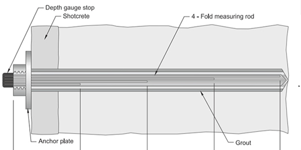
Model EMA-11 measuring anchor has a breaking force of up to 250 kN. The length offered ranges from 3 m to 6 m.
The change in length due to compression or extension between individual measuring bars is taken by measuring the depth of the near end of the respective measuring bars from a reference plate provided at the mouth of the borehole. A digital caliper/micrometer depth gauge with a resolution of 0.01 mm is used to take the readings.
An electrical head assembly consisting of four potentiometric sensors is optionally available for electrical output. Encardio Rite model EDI-53P readout/data logger or EDAS-10 data acquisition system are available for monitoring measuring anchor at the site.
Specifications Of Model EMA-11 Measuring Anchor Add Your Heading Text Here
| Length | 3, 4, 6 m |
| Fixed points | 4 |
| Borehole diameter | 51 mm |
| Anchor diameter | 26.7 mm standard |
| Loading capacity | 250 kN |
| Range | ± 5 mm |
| Resolution | 0.01 mm |
| Enclosure | IP 65 |
This was all about the extensometers from their types, and construction to operating principles, and specifications. Though we tried to cover everything about extensometers, do comment below if we missed something. Also, do let us know your queries or suggestions.