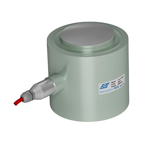
Encardio rite Model ELC-210 Compression load cell is designed for the measurement of loads or forces and finds its application in load measurement in struts. The load applied to the cell can be measured by using any standard digital read-out unit suitable for resistance strain gauge applications.
Let’s look at the compression load cell installation procedure:
Introduction to Compression Load Cell
The interior of the load cell is constructed in a columnar manner. The element instrument is made from martensitic stainless steel and hardened to provide improved linearity and hysteresis.
The strain gauge used in the instrument is foil-type bonded to the elements using a block of special epoxy cement. The sectional area of the columnar construct of the load cell diversified in the different capacity load cells to yield the same mV/V output for a zero to full load.
Using an electron beam welding machine, a cover with a glass-to-metal seal is welded to the element, making the load cell hermetically sealed.
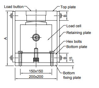
As the load cells are very sensitive to eccentric loading, a top plate of suitable dimension is used to reduce the effect. In some cases, a bottom plate may also be used.
| Capacity kN | Mounting | A mm | Plate 200 Sq. mm B
thickness |
| 1000/1500 | 4 holes dia 13 at 150
Sq. mm | 234 | 32 |
| 2000/2500/3500 | 260 | 45 |
Cable connection
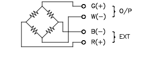
The cable from the Wheatstone bridge circuit ends on a small printed circuit board (PCB) with the help of a six-pin glass-to-metal seal in the cable holder assembly. No-load output balancing, temperature compensation, and full-scale output balancing are done on the PCB.
A suitable four-core shielded cable is terminated through a cable joint housing and cable gland.
Tools & accessories required for load cell installation
The following tools/accessories are required for the compression load cell installation:
- Soldering iron 25 watts, temperature-controlled
- Rosin 63/37 solder wire RF-3C, 30 swg.
- Wire stripper and cable cutter
- Pliers 160 mm 2.2.5 Spanner set
- Digital multi-meter
Compression Load Cell Installation Procedure
Encardio Rite Model ELC-210S compression load cell is specifically constructed for the measurement of compressive load measurement between structural members. The load measurement system of the load cell owes its stability to no moving parts and mechanical linkages. Apart from this, the temperature-compensated quality of the load cell minimizes the effect of temperature variation. The measurement system consists of a junction box, top and bottom mounting plates, cable, switch box, and a readout unit.
Read more: Load Cells: Types, How It Works, Applications, & Advantages
Preparation of Sensor Before Installation
The working of the load cell can be confirmed using the following measures:
- Using a digital multimeter, the resistance measurement between green/white terminals should be 700 Ohm ± 1 %, and between red/black terminals should be 770 Ohms ± 5 %.
- The resistance between the outer casing and any lead should be > 500 M Ohm.
- The zero balance of the load cell using a portable digital indicator should be between ± 0.2 mV/V.
The typical installation method for the measurement of load in Struts
The preparation of site/struts for monitoring of the load cell stars with welding two base plates of 500 mm x 300 mm x 25 mm on the runner beam. The plates function as support to the struts over the runner beam at the arc where the load cells will be mounted. For successfully mounting the load cells, the faces of the struts need to be provided with support plates.
When the struts are placed properly, the load cell assembly is lifted and positioned between flanges at a designated area. The top plate and the bottom fixing plate are welded to the strut flanges.
CAUTION:
Precautions must be taken to avoid damage to the load cell by the heat during the welding procedure. To avoid an unnecessary rise in temperature, rags soaked in water should be wrapped around the load cell. To avoid permanent damage to the strain gages, make sure there is no direct path for the current to pass through the load cell during the welding process.
Read more: Strain Gauge Type Load Cell- Introduction & How it Works?
NOTE:
The struts contractor takes care of the preparation of suitable struts for mounting of load cell and providing appropriate tie rods, base plates, and support plates. The tie rods can be round, flat bars, or angle iron. With the decision of the ER installation personnel, the compression load cell installation process can be altered to suit the final load cell mounting schemes and site conditions.

The strutting professional should install the load cells in struts under supervision. The installation may need to make the necessary changes in the strutting system, equipping shim plates for filling any gaps, etc. such that load transfer to load cell is ensured.
Once the load cell system is installed, it is advised to remove the two retaining plates. Check the working of the load cell by pre-loading the system and marking the readings. In case the readings exceed the specified limit, corrective measures should be taken.
Using an adhesive lined or blind riveted cable clamps, attach the signal cable from the load cell to the steel surface. The cable should then be routed to the local junction box. Allow the adhesive bonds to gain full strength by avoiding unneeded use of the cable for at least 24 hours.
Place a junction cum switch box at a convenient location from where the load cell reading can be taken without any hindrance from rain, wind & sunlight. Use a protective cover for a complete shield.
The load cell cable originating from the local junction box should be terminated in the switch box which has ten input cable glands. The input glands which are not in use should be blocked. Using the four-pin corrected, readings should be taken.
Re-check the load cell readings with the EDI-53L read-out unit or with another read-out unit.
NOTE: Using suitable tags, sensors, cables, and switch boxes should be marked. A temporary way to do it is to write the serial/code number and location of a piece of paper, placing it on the item using transparent cello tape. For a more permanent mark, use paint.
CAUTION:
Precautions should be taken to keep the installed load cell, junction box, cable, and switch box away from direct sunlight, wind effects, water, and mechanical damage caused by normal construction activity, vehicular traffic, and vandalism.
Read more: Centre Hole Load Cell Installation: Preparation & Troubleshooting
Troubleshooting installation problems
The compression load cell installation is done with precision and care as the corrective actions are limited. Maintenance and troubleshooting are consequently confined to periodic checks of cable connection and functioning of the read-out unit.
Here are some solutions to general problems.
Symptom: Load cell reading unstable
- Make sure the resistance between any lead and outside casing is more than 500 M Ohm. If the desired result does not show, cut around a meter length of cable from the end and check again.
- Connect the portable digital indicator with another load cell to make sure it functioning properly. If not, consult the manual of strain indicator for troubleshooting instructions.
- Use a different portable digital indicator to take the reading.
- Make sure there is no source of electrical noise nearby such as motors, generators, transformers, arc welders, and antennas. If so shield the instrument from the noises.
Symptom: Load cell fails to read
- The cable may likely be cut or crushed. Using a digital multimeter, check the resistance measurement between green/white terminals which should be 700 Ohm ±1 %, and between red/black terminals which should be 770 Ohms ± 5 %. If the cables are long, add cable resistance when checking resistance (multiply by 2 for both leads). An infinite reading of the resistance pertains to a cut in the cable while a low resistance reading means there is a short in the cable.
- Connect the portable digital indicator with another load cell to make sure it functioning properly. If not, consult the manual of strain indicator for troubleshooting instructions.
- Make use of another portable digital strain indicator to take the reading.
Read more: Load Cells: Types, How It Works, Applications, & Advantages
This was about compression load cell installation, cable laying, and troubleshooting problems. If you’ve any doubts or questions, feel free to drop them in the comment section below.