Encardio Rite model ELC-30S Centre hole load cell is a precision-engineered instrument used to measure tensile force in a ground anchor, rock bolt, cable, or tie back. It is also used in the measurement of compressive load between structural members, i.e. tunnel supports or at the junction between a beam and the top of a pile strut.
Preparation of sensor before load cell installation
To give way to the six-pin terminal, remove the cable joint housing from the edge of the sensor. We only make use of four terminals. The active ones are marked with red, green, black, and white dots. Make sure to clean the terminals using a toothbrush.
NOTE: Make sure you’re not making use of acetone for cleaning the terminals as it may hamper the glass-to-metal seal. However, you can use acetone for other parts of the sensors. Here’s how you can check if the sensors are working accurately.
- Measure the resistance using a digital multimeter. It should be 770 Ohm ± 5 % between red/black terminals and 700 Ohm ± 1 % between green/white terminals.
- On the other hand, the resistance between the outer casing and any lead should be greater than 500 M Ohm.
- Measure the zero balance of the load cell using a portable digital indicator. If it is between ± 0.2 mV/V, then the sensor is working properly.
NOTE: Make sure your sensors are working properly before moving on to the load cell installation procedure.
To stay on the cautious side, inspect the cable visually for any cuts or damaged sheath. Add a meter extra length for cable jointing before cutting the cable. It is important to ascertain the correct length of the cable and the cable jointing should be avoided as much as possible.
Read more: Vibrating Wire Load Cell- Introduction & Operating Principle
CAUTION: While removing the cable, use a spool and do the task by rotating the spool. This eliminates the chances of bending, twisting, or nicking of the cable.
The next step is to connect the required length of cable to the sensor. Follow the same procedure as described above to check the working of the sensor.
NOTE: Remember to adjust cable resistance when checking resistance between leads after cable jointing.
Eg: For the EC-0107 cable (7 x 0.25 conductor) resistance is around 49 Ohm/km (multiplied by 2 for both leads). Similarly, make the essential change in the resistance in case of any other cable.
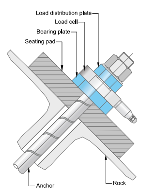
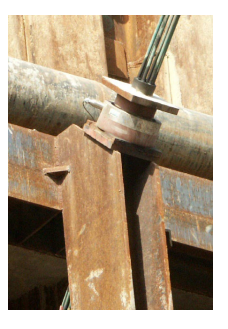
Before mounting the load cell, it is important to note that the load cell assembly is always mounted on a machined seating pad which has a thickness greater than the flat bearing plate.
The seating pad is filled in with grout perpendicular to the axis of the anchor, keeping the top surface on the ground.
In the case of the Centre Hole Load Cell, it should be installed between load distribution plates & flat bearing.
The plates should be placed parallel to each other and normal to the axis of the load cell. The anchor is centralized by carefully placing the load cell over it.
Using another way, a befitting bush can be placed in the annular space between the load cell and anchor. However, care should be taken to ensure that the bush does not interfere with the loading pattern of the load cell.
In places where the load distribution plates and flat bearing cannot be fixed parallel to each other, wedges, spherical settings, or compensation washers made of copper/high-density plastic material should be used.
NOTE: There are a few factors that can affect the load cell reading like eccentric loading, uneven or warped bearing, and load distribution plates.
The effect can be reduced by using thicker top and bottom plates. Applying the rule of thumb, use 23, 35, 45, 55, and 65 mm thick top and bottom plates for the 200, 500, 1000, 1500, and 2000 kN load cells respectively.
The effect of eccentric loading is diminished when the load cell is carefully mounted. To make sure the load cell is mounted accurately, it should be placed between the flat bearing top and bottom plates of proper thickness depending upon the load cell capacity.
Read more: Strain Gauge Type Load Cell- Introduction & How it Works?
For improved performance, the bearing and load distribution plates are ground flat. The instrument should be centralized concerning the load cell axis. In case the surfaces are not parallel, spherical settings or wedges should be employed.
Deformable materials like Compensation washers made of copper, and high-density plastic can also be used.
After mounting the load cell, pre-tension it by connecting the portable digital indicator to the load cell and monitoring the load while tensioning the anchor bolt or the cable anchor.
NOTE: As stated before, the accuracy of the reading can be influenced by an uneven bearing or load distribution plate, or by bending or distortion of plates. Make sure to use the bearing/load distribution plates of the prescribed thickness and finish, keeping in mind that the hole in the load distribution plate should equal the internal diameter of the Centre hole load cell.
An experiment was conducted to measure the effect of bearing/load distribution plates bending using the Encardio Rite 500 kN Centre hole load cell. The instrument was loaded on a universal testing machine to full capacity. To illustrate the experiment, a flat plate was laid on the load cell while the load was applied using brushes of different diameters.
The result which came forward confirmed that by using thick bearing and load distribution plates, the effect is reduced.
Load Cell Installation- Cable Laying
General precautions in laying cable:-
Great care and skills must be used while laying down the cable for load cell installation. A good portion of the cable and the load cell/cable joint may be exposed to blasting & rigid construction environment. Therefore, they must be well-protected.
Some part of the cable is embedded permanently, eliminating the availability of future access for any maintenance or corrective action. However, the procedure for laying cables is different when installing the instrument in different places.
There are some common points for all installations:
- Precautions must be taken to keep the cable well-protected from any damage due to angular and sharp particles of material that may be present in the embedment.
- Even though the cables can be spliced without affecting the reading of the sensors, it should be avoided wherever possible. If necessary, special cable jointing kits can be used.
The cables should be properly marked, onward from the point from which they come out of the load cell. Even while taking strict precautions, some errors are bound to occur. The tags may be misplaced due to the accidental cutting of the cable.
Read more: Load Cells: Types, How It Works, Applications, & Advantages
To reduce errors and mistakes, Encardio Rite has come up with a convention. It states that looking from the junction box or the observation room towards the sensor, the cable from the most distant sensor is always on the left-hand side. Following this, the cable from the nearest sensor is placed at the extreme right.
NOTE: A simple code for remembering the above convention is “LL-SR”. Longer (cable) left, shorter (cable) right when viewing the sensors from the observation room.
CAUTION: All the cables should be tagged after every 5m using a non-corrosive material like stainless steel or plastic.
CAUTION: Another Encardio Rite convention states that the cable from the most distant sensor should be connected to the extreme left socket in the junction box. Succeeding cables from the sensors are connected progressively towards the right in the junction box.
All the wiring should be neat and professional. If needed, it must be passed through MS/Copper/PVC solid or flexible tubing that should be clamped to the mainframe at suitable intervals. This helps to keep the cables protected from any unseen damage.
Load Cell Installation – Troubleshooting
Once the load cell is installed, remedial action is limited.
The periodic checks of cable connection and the functioning of the read-out unit help in the maintenance and troubleshooting.
Here are a few problems that can be troubleshooted.
Symptom: Load cell reading unstable
- Check the insulation resistance, making sure that the resistance between any lead and outside casing should be > 500 M Ohm. If the desired output is not met, cut about a meter or so from the end of the cable and check again.
- To make sure the digital indicator is not malfunctioning, use it with another load cell. If the problem persists, consult the manual of strain indicator for troubleshooting instructions.
- Another portable digital indicator can be used to take the reading.
- If there is any source of electrical noise like motors, generators, transformers, arc welders, and antennas, it could be shielded to reduce the noise.
Symptom: Load cell fails to read
- One of the reasons for this may be that the cable has been cut or crushed. Check resistance between leads with a digital multimeter. It should be 770 Ohm ± 5 % between the red/black leads and 700 Ohm ± 1 % between the green/white leads. In case of infinite or very high value, a cut in the cable may be a possibility. On the other hand, if the resistance reads below 100 Ohm, a short in the cable is likely.
- To make sure the digital indicator is not malfunctioning, use it with another load cell. If not, the indicator may be malfunctioning. Consult the manual of strain indicator for troubleshooting instructions.
- Use another portable digital strain indicator to take the reading.
This was all about load cell installation, cable laying, and troubleshooting problems.