Encardio Rite Model EAN-41M is a MEMS tilt sensor (beam sensor) designed for monitoring the inclination and vertical rotation of structures. Any change in a structure that is caused due to construction activity like excavation; tunneling or de-watering that may affect the ground supporting the structure is called a tilt change.
It may also be due to the loading of the structure, such as the loading of a dam during impoundment, the loading of a diaphragm wall during excavation, or the loading of a bridge deck due to wind and traffic. The Data collected from the tiltmeter provide an early warning of possible threatening deformations, giving sufficient time to take corrective measures or evacuation of the area, if necessary.
Tilt Sensor Application
If you’re wondering where tilt sensors are used, they are used in the following monitoring activities:
- Monitoring the vertical rotation of retaining walls.
- Monitoring inclination and rotation of dams, piers, piles, and other structures.
- Monitoring the stability of structures in landslide areas.
- Monitoring tunnels for convergence and other movements.
- Monitoring the safety of structures around zones of excavation or tunneling.
- Monitoring deflection in bridges and struts under different loading conditions
Operating Principle – How does a tilt sensor work?
 Tilt-beam-sensor
The tilt sensor working principle is built around the Micro-electromechanical system (MEMS). Encardio Rite Model EAN-41M beam sensor has a range of ±15°, along with high sensitivity and tilt sensor accuracy mounted inside an aluminum enclosure (beam). It provides a bipolar DC voltage output proportional to the sine of the tilt angle measured by the tiltmeter. The output is zero volts for a truly vertical position.
The MEMS tilt sensor gives a comparatively low-cost tilt measurement solution and yet offers excellent resolution and long-term stability. With the help of mounting accessories like brackets and anchors, the tiltmeter can be secured on any vertical surface, horizontal floor, or ceiling.
Read more: Inclinometer: Types, How It Works, & Uses
Model EAN-41M Tilt Sensor is not designed to measure the absolute determination of the tilt of structures. It measures the change in the tilt of a structure to which it is fixed. Once the instrument is mounted on the structure, the initial tilt reading is noted. Subtracting the initial tilt reading from subsequent tilt readings gives the change in the tilt of the structure over a period of time.
How to install tilt sensors?
Encardio Rite Model EAN-41M can be installed on horizontal as well as vertical surfaces. Let’s start with the installation of horizontal structures.
Tools and accessories required for installation
- Sensor mounting kits, one more than the number of beams to be mounted in series.
- Two open-ended spanners of 17 mm size and one open-ended spanner of 13 mm size, or two adjustable wrenches.
- One flat-head screwdriver with a 4 mm blade width.
- Quick set epoxy grout for grouting the anchors in concrete.
- Loctite 290 threads sealant or any other equivalent post-assembly thread sealant.
- Percussion or hammer drill with a 12 mm drill bit.
- Chalk line and colored chalk.
- Tape measure, longer than the maximum beam gauge length to be used.
- Spirit level.
Installation of Horizontal Tilt Sensor
Installing the anchors
 Anchor-installation
Horizontal sensors are designed to discover the relative vertical displacement of the two anchors at their ends. The distance between the two anchors is known as the gauge length of the tilt sensor. They are usually available in standard gauge lengths of 1, 2, or 3 m, but varied specified lengths are also available.
The sensors are generally used in a string with two tilt sensors sharing a common anchor for fixing.
- Identify and mark the point where you want the sensors placed with the help of a chalk line and suitable coloured chalk. In the case of wall mounting, make use of a spirit level and a beam to ensure that the line is as horizontal as possible. As for floor mounting, the line should be in sync with the direction of the vertical settlement profile.
- Mark off distances corresponding to the gauge length of the beams to be fixed, using a tape measure. Keep in mind that the beams are somewhat longer than their gauge length. If wanted, beams of different gauge lengths may be used in the same string. Each mark corresponds to an anchor position.
- With the help of a drilling machine, dig 12 mm diameter anchor holes to a depth of about 100 mm at the marked positions making sure that the holes are perpendicular to the wall or floor surface.
- Blow air or brush the debris, making the hole clear.
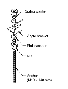
- With the help of epoxy grout in these holes, place the longer (148 mm) anchors (Figure 2) of the mounting kits in such a way that the 50 mm length of anchors projects out of the surface after fixing.
- Let the grout settle for the required amount of time before handling it.
- Measure & record the exact center-to-center distances between each anchor in the string.
Read more: Tiltmeter: How Does it Work, Installation, & How to Read
Fixing the beams
Each sensor is equipped with two mounting angles on each side. The beams can be fixed to the anchors directly using these mounting angles.
However, in case the strings of beams are subject to any torsional movement, use the separately available beam mounting kits as it provides more flexibility.
The figure below shows the correct position of each component of the kit while mounting the beams.
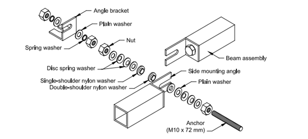
- Attach the angle brackets to the already grouted 148 mm anchors. Check the relative position of the nuts, washers, and angle brackets from the drawing.
- Secure the 72 mm, stud anchors, on the angle brackets that are fixed to the grouted anchors.
- By loosening the hex nut holding it to the beam, partially release the mounting angle at both sides of each beam.
- As shown in the drawing, fix the beams on the 72 mm stud anchors. Use the double-shouldered nylon washer between the mounting angles of two adjacent beams.
- Gradually tighten the nuts to ensure that the spring washers are compressed.
- Tighten the bolt head holding the mounting angles to the beam ends.
- Set a drop of Loctite 290 (post-assembly thread locking compound) at the accessible junction of each nut on the studs to lock them in place.
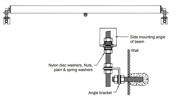
The figure below shows how to mount the EAN-41M horizontal tilt sensor on the wall using the standard mounting kit.
 horizontal-beam-sensor
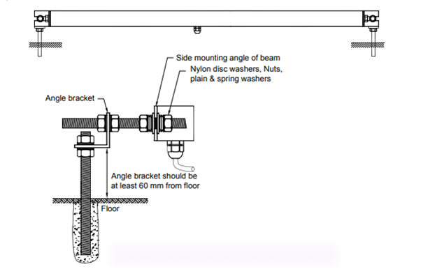
The figure below showcases how to mount the EAN-41M horizontal tilt sensor on the floor using the standard mounting kit.
Installation of Vertical Tilt Sensors
Vertical tilt sensors find their application to determine the relative horizontal displacement of the two anchors at their ends. Similar to the horizontal tilt sensor, the vertical sensors are generally supplied in standard gauge lengths of 1, 2, or 3 m, but other customer-specified lengths are also available.
These sensors are commonly used in a string with two sensors sharing a common anchor for fixing. Vertical tilt sensors consist of a standard EAN-41M tiltmeter, an aluminum beam, 38 mm x 38 mm square and specified gauge length, and mounting hardware for mounting the tiltmeter on the beam, generally packed separately for shipment.
Installing the anchors
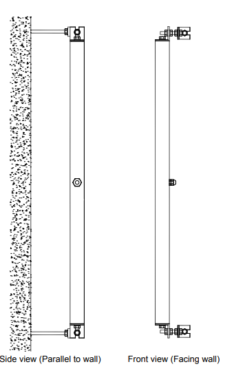 vertical-beam-sensor
- With the help of a plumb line or suitable coloured chalk, identify and mark a vertical straight line along which the sensors would be fixed.
- Mark off distances corresponding to the gauge length of the beams to be fixed, using a tape measure. Keep in mind that the beams are somewhat longer than their gauge length. If wanted, beams of different gauge lengths may be used in the same string. Each mark corresponds to an anchor position.
- With the help of a drilling machine, dig 12 mm diameter anchor holes to a depth of about 100 mm at the marked positions making sure that the holes are perpendicular to the wall or floor surface.
- Blow air or brush the debris, making the hole clear.
- Fix the longer (148 mm) anchors of the mounting kits with suitable epoxy grout in these holes such that around 50 mm length of anchors projects out of the surface after fixing.
- Allow the grout to set for the recommended time before handling.
- Measure and record the exact center-to-center distances between each anchor in the string.
The procedure for fixing the beams is the same as the one described for horizontal surfaces.